Compressor terminal plate

a terminal plate and compressor technology, applied in the field of compressors, can solve the problems of difficult control of manufacturing costs, wiring difficulties of hermetic compressors,

Active Publication Date: 2012-11-27
CARRIER CORP
View PDF23 Cites 7 Cited by
  • Summary
  • Abstract
  • Description
  • Claims
  • Application Information

AI Technical Summary

Benefits of technology

[0021]However, for the terminals, the machining includes machining of the counterbores 136 (FIG. 4) with a tool inserted through the open upstream / suction side end (either before or after machining the face 49 thereon). The machining may also include machining a flat plateau surface 168 surrounding the group of bores 132 and counterbores 136 (e.g., before machining at least the counterbores). The angling helps provide clearance for the tools doing the internal machining. As viewed in FIG. 4, clearance is relative to a portion of the mounting flange to the left and upper and lower wall segments of a stator bore to the right, both extending to the face 49. The stator bore retains a downstream portion of the stator to ensure coaxiality with the rotor 26. The counterboring provides a counterbore base surface at a precise and consistent separation T from the face 120. This permits precise positioning of the terminals. This also avoids sealing problems associated with mounting the terminals in a plate separate from the casting and which must be sealed thereto by additional means. The angling may provide additional use benefits. For example, as shown in FIG. 3, a major portion of the exposed pin lies inboard of the projection 520 of the perimeter 170 of the flange 152. This may help reduce chances of damage to the pins.

Problems solved by technology

Hermetic compressors present difficulties regarding their wiring.
Routing of conductors through the housing while maintaining hermeticity and convenience of use while controlling manufacturing costs present difficulty.

Method used


Image

  • Compressor terminal plate
  • Compressor terminal plate
  • Compressor terminal plate

Examples


Embodiment Construction

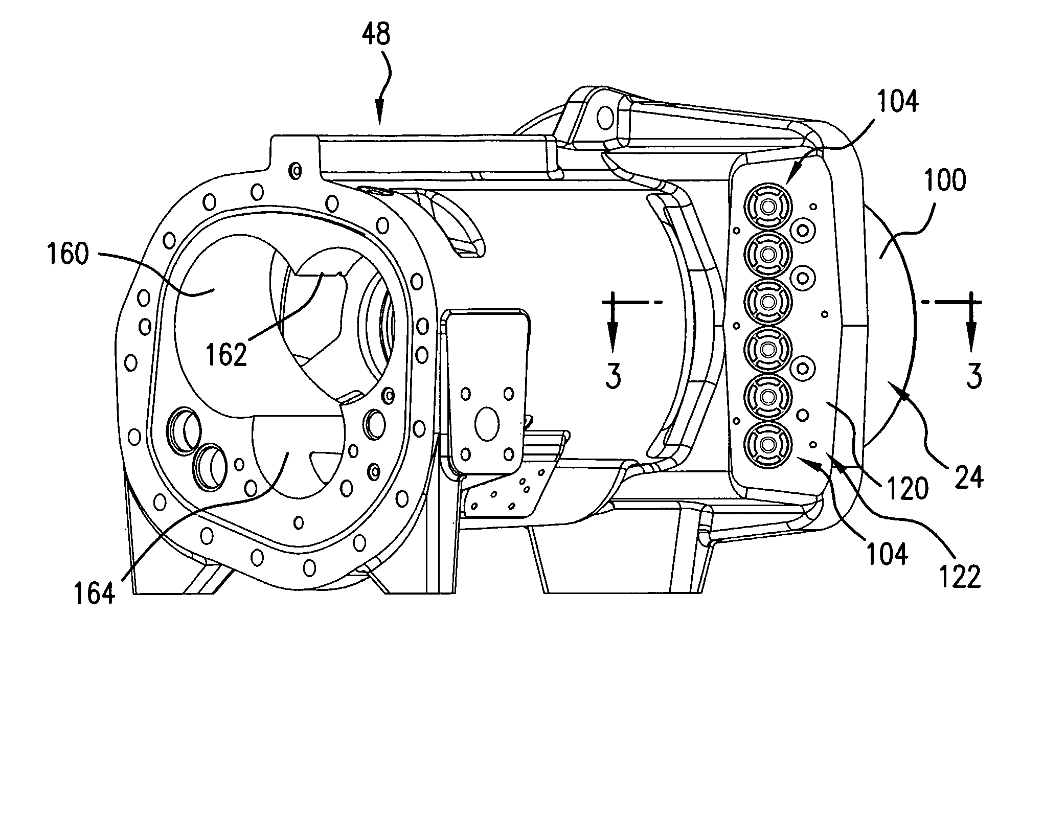
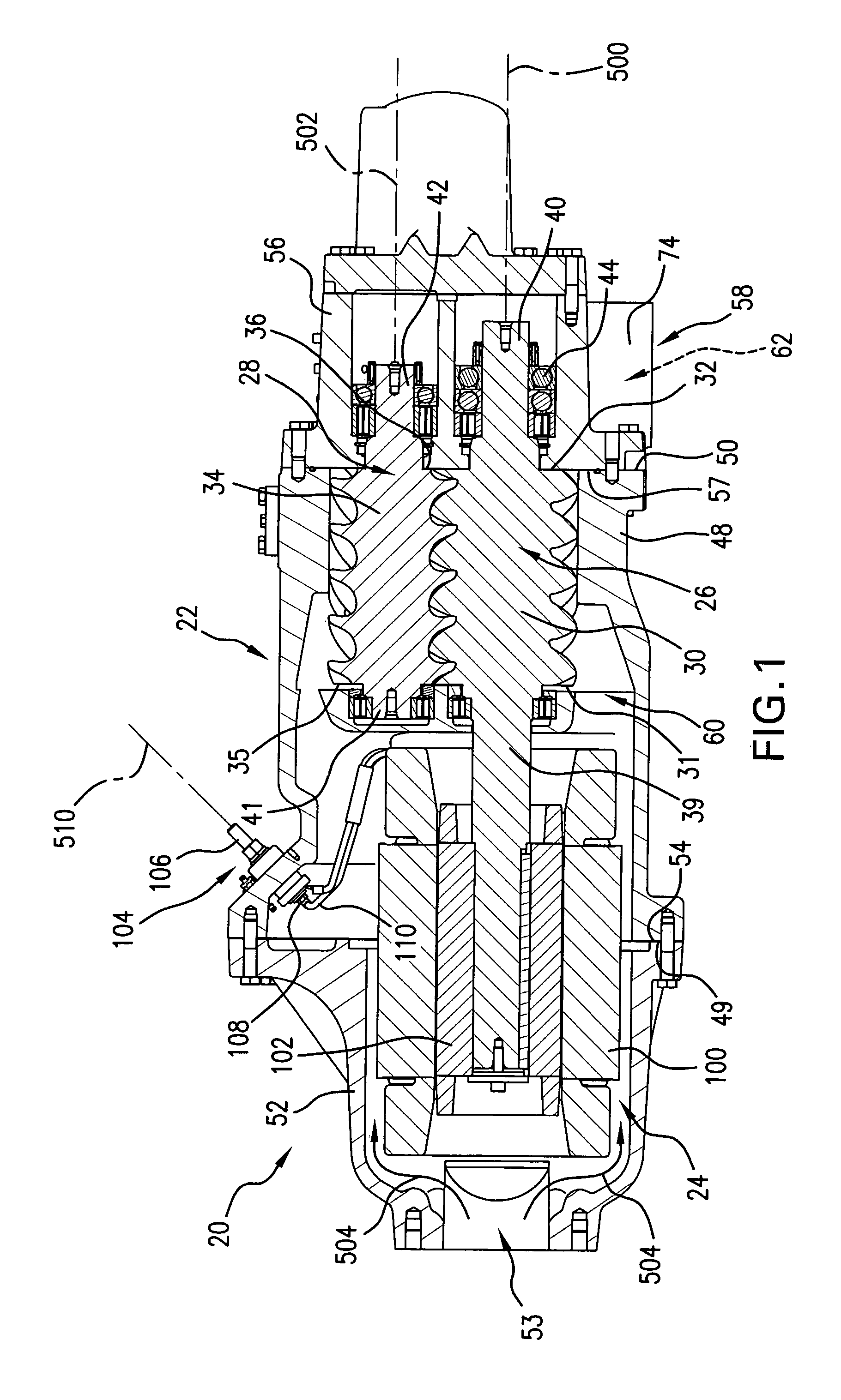
[0014]FIG. 1 shows a compressor 20 having a housing assembly 22 containing a motor 24 driving rotors 26 and 28 having respective central longitudinal axes 500 and 502. In the exemplary embodiment, the rotor 26 has a male lobed body or working portion 30 extending between a first end 31 and a second end 32. The working portion 30 is enmeshed with a female lobed body or working portion 34 of the female rotor 28. The working portion 34 has a first end 35 and a second end 36. Each rotor includes shaft portions (e.g., stubs 39, 40, 41, and 42 unitarily formed with the associated working portion) extending from the first and second ends of the associated working portion. Each of these shaft stubs is mounted to the housing by one or more bearing assemblies 44 for rotation about the associated rotor axis.

[0015]In the exemplary embodiment, the motor is an electric motor having a rotor and a stator. One of the shaft stubs of one of the rotors 26 and 28 may be coupled to the motor's rotor so a...


PUM

PropertyMeasurementUnit
θaaaaaaaaaa
θaaaaaaaaaa
angleaaaaaaaaaa

Abstract

A compressor (20) has a housing (22) having first (52) and second (48) members. A motor (24) within the housing (22) is coupled to one or more working elements (26, 28) to drive the one or more working elements (26, 28) to compress a fluid. A number of electrical terminals (104) are each mounted in an associated aperture (132) in the second housing member (48) and electrically connected to the motor (24).

Description

BACKGROUND OF THE INVENTION[0001]The invention relates to compressors. More particularly, the invention relates to hermetic refrigerant compressors.[0002]Screw-type compressors are commonly used in air conditioning and refrigeration applications. In such a compressor, intermeshed male and female lobed rotors or screws are rotated about their axes to pump the working fluid (refrigerant) from a low pressure inlet end to a high pressure outlet end. During rotation, sequential lobes of the male rotor serve as pistons driving refrigerant downstream and compressing it within the space between an adjacent pair of female rotor lobes and the housing. Likewise sequential lobes of the female rotor produce compression of refrigerant within a space between an adjacent pair of male rotor lobes and the housing. The interlobe spaces of the male and female rotors in which compression occurs form compression pockets (alternatively described as male and female portions of a common compression pocket j...

Claims


Application Information

Patent Timeline
Patent Type & Authority Patents(United States)
IPC IPC(8): F04B17/03H02K11/00
CPCF01C21/10F04C18/086F04C18/16F04C23/008Y10T29/49242F04C29/045F04C2240/803F04C29/0085
Inventor PILESKI, PETER J.FRASER, BRUCE A.
Owner CARRIER CORP
Why Eureka
Try Eureka