Zoom lens system, imaging device and camera

a zoom lens and imaging device technology, applied in the field of zoom lens systems, can solve the problems of unsatisfactory digital requirements, zoom lenses and variable magnification optical systems, and the overall length of the lens system is not desirable, and achieves the effects of short overall length of the lens system, high zooming ratio, and high resolution

Inactive Publication Date: 2012-11-27
PANASONIC CORP
View PDF46 Cites 53 Cited by
  • Summary
  • Abstract
  • Description
  • Claims
  • Application Information

AI Technical Summary

Benefits of technology

[0011]An object of the present invention is to provide: a high-performance zoom lens system that has a high resolution and a relatively high zooming ratio and still has a short overall length of lens system because of a small number of lens elements constituting the lens system; an imaging device employing this zoom lens system; and a thin and compact camera employing this imaging device.
[0155]The present invention provides: a high-performance zoom lens system that has a high resolution and a relatively high zooming ratio and still has a short overall length of lens system because of a small number of lens elements constituting the lens system; an imaging device employing this zoom lens system; and a thin and compact camera employing this imaging device.

Problems solved by technology

However, among the zoom lenses and the variable magnification optical systems disclosed in the above-mentioned patent documents, some have a relatively short overall length of lens system because of a small number of lens elements constituting the lens system but have a low zooming ratio less than 3, while others have a relatively high zooming ratio but have an undesirably long overall length of lens system because of a large number of lens elements constituting the lens system.
Thus, these zoom lenses and variable magnification optical systems do not satisfy the requirements for digital cameras in recent years.

Method used


Image

  • Zoom lens system, imaging device and camera
  • Zoom lens system, imaging device and camera
  • Zoom lens system, imaging device and camera

Examples


numerical example 1

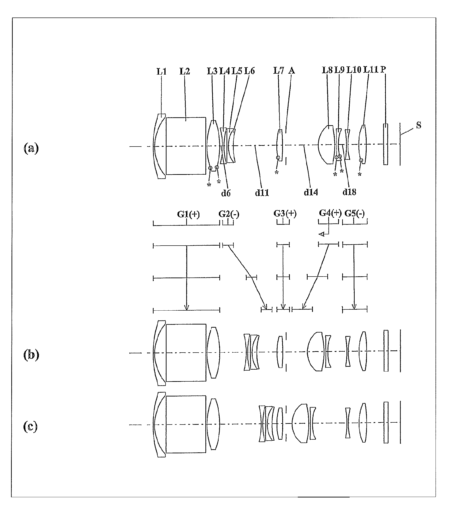
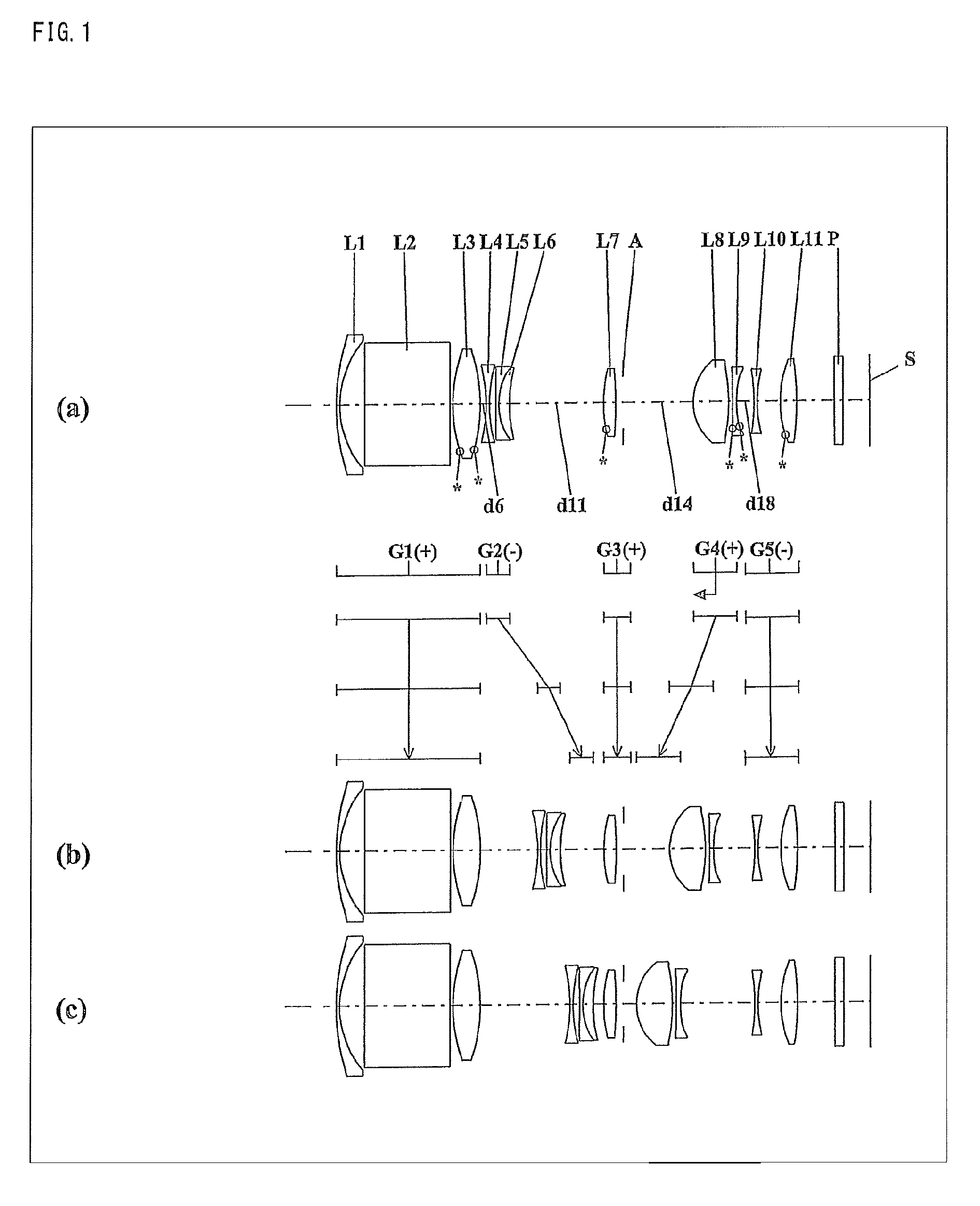
[0334]The zoom lens system of Numerical Example 1 corresponds to Embodiment 1 shown in FIG. 1. Table 1 shows the surface data of the zoom lens system of Numerical Example 1. Table 2 shows the aspherical data. Table 3 shows various data.

[0335]

TABLE 1(Surface data)Surface numberrdndvdObject surface∞ 122.363200.300001.9228620.9 29.403002.43850 3∞8.411501.8466623.8 4∞0.30000 5*13.961202.693501.5833259.1 6*−16.32610Variable 7−14.846400.300001.9108235.2 813.347500.62170 9−342.82120 0.300001.6779055.5105.799901.052301.9228620.91113.81180Variable12*11.544101.200001.5299655.813−36.882900.7000014(Diaphragm)∞Variable155.206503.468001.4970081.616−17.462700.4000017*82.834800.400001.5838730.918*11.01620Variable19−18.995000.300001.9228620.92011.917102.3266021*10.444201.642401.5299655.822−28.202103.7604023∞0.900001.5168064.224∞(BF)Image surface∞

[0336]

TABLE 2(Aspherical data)Surface No.5K = 0.00000E+00, A4 = −7.52903E−05, A6 = −4.94683E−08, A8 = −2.70038E−09 A10 = −9.28591E−10, A12 = 0.00000E+00Surf...

numerical example 2

[0338]The zoom lens system of Numerical Example 2 corresponds to Embodiment 2 shown in FIG. 4. Table 4 shows the surface data of the zoom lens system of Numerical Example 2. Table 5 shows the aspherical data. Table 6 shows various data.

[0339]

TABLE 4(Surface data)Surface numberrdndvdObject surface∞ 138.587800.52000 1.9228620.9 212.210401.73360 3∞8.59640 1.8466623.8 4∞0.30000 5*10.301302.62640 1.5833259.1 6*−18.82220Variable 7−50.784100.40000 1.9108235.2 87.668101.13090 9−10.674100.40000 1.7550052.31012.619300.99710 1.9459518.011−99.30630Variable12*9.722401.20000 1.5441056.113−67.397400.7000014(Diaphragm)∞Variable155.736803.05120 1.4970081.616−19.431000.8331017*−54.387300.60000 1.6074027.018*22.17810Variable19455.226500.40000 1.9228620.9208.001202.6881021*8.240101.61380 1.5441056.122*161.922303.7514023∞0.90000 1.5168064.224∞(BF)Image surface∞

[0340]

TABLE 5(Aspherical data)Surface No.5K = 0.00000E+00, A4 = −1.87045E−04, A6 = 4.59316E−06,A8 = −2.32580E−07 A10 = 4.35310E−09, A12 = 0.00000...

numerical example 3

[0342]The zoom lens system of Numerical Example 3 corresponds to Embodiment 3 shown in FIG. 7. Table 7 shows the surface data of the zoom lens system of Numerical Example 3. Table 8 shows the aspherical data. Table 9 shows various data.

[0343]

TABLE 7(Surface data)Surface numberrdndvdObject surface∞ 125.555500.300001.9228620.9 210.544101.98790 3∞8.56210 1.8466623.8 4∞0.30000 5*10.749602.75970 1.5833259.1 6*−17.31600Variable 7−29.891500.30000 1.9108235.2 88.499500.99360 9−13.661400.300001.7462451.4109.945100.945951.9459518.011115.60180Variable12*9.111101.20000 1.5441056.113−172.226300.7000014(Diaphragm)∞Variable155.704303.12090 1.4970081.616−19.905000.5502017*34.484400.50000 1.6074027.018*11.30600Variable19−58.930600.40000 1.9228620.92010.050902.6754021*8.131101.53330 1.5441056.122*55.322303.8800023∞0.90000 1.5168064.224∞(BF)Image surface∞

[0344]

TABLE 8(Aspherical data)Surface No.5K = 0.00000E+00, A4 = −1.58141E−04, A6 = 4.21542E−06,A8 = −2.08493E−07 A10 = 4.17040E−09, A12 = 0.00000E+00...


PUM


Abstract

A zoom lens system, in order from an object side to an image side, comprising a first lens unit having positive optical power, a second lens unit having negative optical power, a third lens unit having positive optical power, and subsequent lens units including a fourth lens unit having optical power, wherein any one of the first lens unit, the second lens unit, the third lens unit, and the subsequent lens units includes a lens element having a reflecting surface that bends a light beam incident from an object, wherein in zooming from a wide-angle limit to a telephoto limit at the time of image taking, the first lens unit and the third lens unit do not move along an optical axis, and wherein the condition is satisfied: 1.42<nd4ave<1.58 (nd4ave is an average of refractive indices to the d-line of the lens elements constituting the fourth lens unit), an imaging device and a camera are provided.

Description

CROSS-REFERENCE TO RELATED APPLICATION[0001]This application is based on application Nos. 2009-236424 and 2009-236426 filed in Japan on Oct. 13, 2009, the contents of which are hereby incorporated by reference.BACKGROUND OF THE INVENTION[0002]1. Field of the Invention[0003]The present invention relates to a zoom lens system, an imaging device, and a camera. In particular, the present invention relates to: a high-performance zoom lens system that has a high resolution and a relatively high zooming ratio and still has a short overall length of lens system (a distance on the optical axis, from an object side surface of a lens element located on the most object side of the lens system, to the image surface) because of a small number of lens elements constituting the lens system; an imaging device employing this zoom lens system; and a thin and compact camera employing this imaging device.[0004]2. Description of the Background Art[0005]Size reduction and performance improvement are stron...

Claims


Application Information

Patent Timeline
Patent Type & Authority Patents(United States)
IPC IPC(8): G02B15/14
CPCG02B13/18G02B15/173G02B15/145113
Inventor MATSUMURA, YOSHIOIWASHITA, TSUTOMUKURIOKA, YOSHIAKIYAMAGUCHI, SHINJI
Owner PANASONIC CORP
Why Eureka
Try Eureka