Signalling method and apparatus

a technology of signaling and apparatus, applied in the direction of instruments, surveying, borehole/well accessories, etc., can solve the problem of placing limits on the available bandwidth, and achieve the effect of reducing the effect of electrical interference and usable bandwidth

Active Publication Date: 2012-11-27
BAKER HUGHES INC
View PDF3 Cites 0 Cited by
  • Summary
  • Abstract
  • Description
  • Claims
  • Application Information

AI Technical Summary

Benefits of technology

[0006]The present invention seeks to overcome this limitation and provide a signalling system that can cope with such an extremely low quality transmission path, provide a usable bandwidth, and substantially mitigate the effects of electrical interference.
[0012]It is preferred if the alternating signal levels are constant. This ensures that each rising edge is identical to the next, and each falling edge is identical to the next. This greatly improves the ability to correlate the edge patterns accurately.
[0015]A double binning arrangement can also be used. For example, if it is desired to send a value of (for example) 1057, a first signal could indicate that the information is in a range 1000-1999 and a second signal could specify 57 as opposed to 56 or 58. By adding the signals together, the intended output of 1057 is obtained. This can provide greater efficiency in the usage of bin sizes. It can be arranged that a digitised signal (as above) shows the coarse level (eg. 1000, 2000, 3000 etc.) followed by further signal (analogue or digital) for the fine resolution. This can be of great benefit. If for example the “noise” in the signal transmission system is 1 ms, and the time between edges varies from 1 second to 2 seconds, according to the measured signal, then a 0-10,000 psi measured value will be encoded in a 0 to 1000 ms second window, with 1 ms of noise. This would give a noise of 10 psi. However, if a coarse level is transmitted first that specifies the coarse range (0-999, 1000-1999 etc.), then a subsequent analogue signal need only span from 0-1000 psi and hence the overall noise would be 1 psi.

Problems solved by technology

The transmission path can be imperfect, for example inductive, without impairing the efficiency of such a system, although this will place limits on the available bandwidth.

Method used


Image

  • Signalling method and apparatus
  • Signalling method and apparatus
  • Signalling method and apparatus

Examples


Embodiment Construction

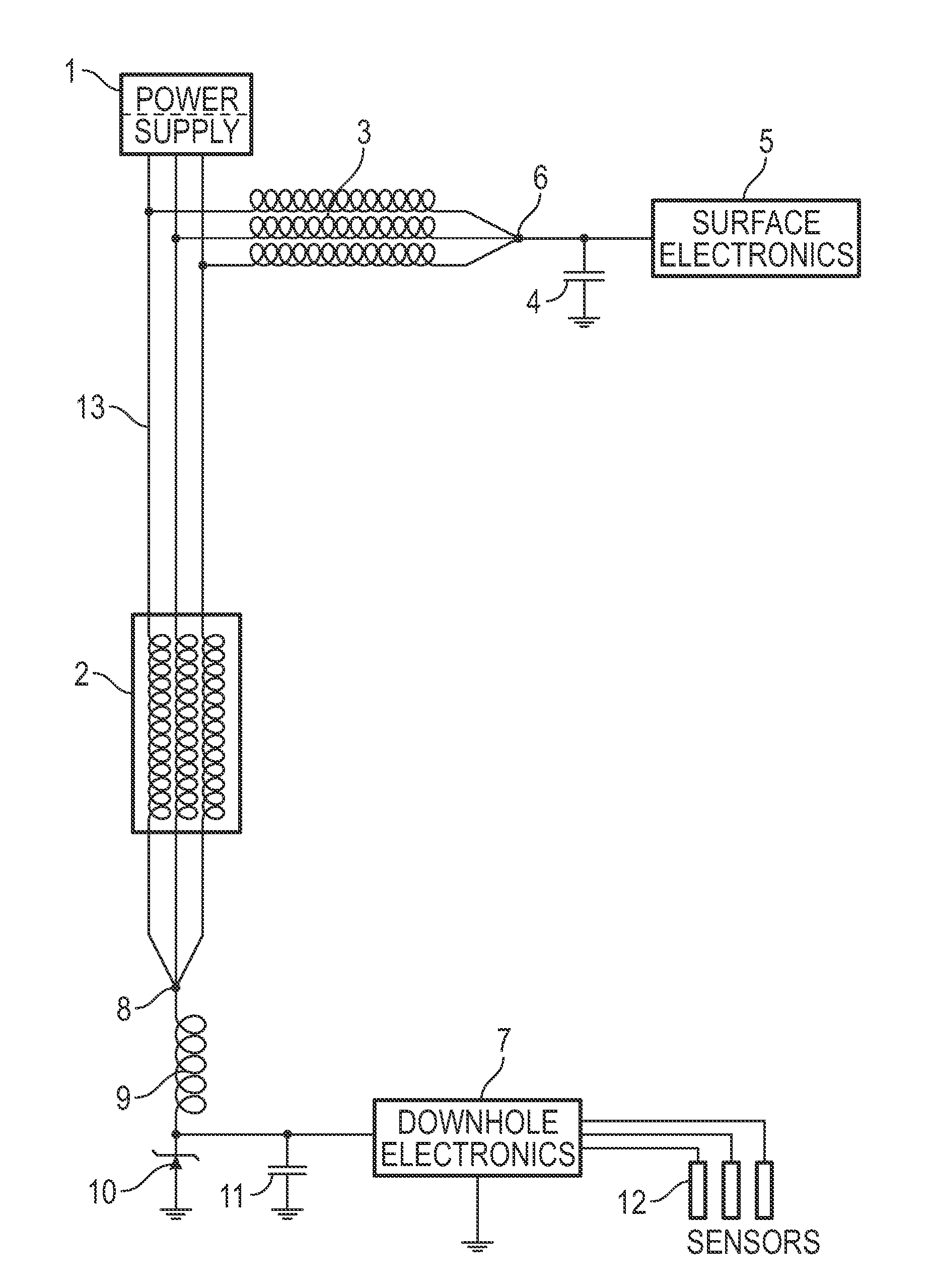
[0022]FIG. 1 shows a downhole motor 2 connected via a downhole 3-phase power cable 13 to a surface isolated power supply 1. This system is used to assist the flow of oil up the well.

[0023]A downhole instrument, consisting of downhole electronics 7, sensors 12, capacitor 11, zener diode 10 and downhole inductor 9 is attached to the neutral point 8 of the downhole motor 2.

[0024]Surface electronics 5 are attached to surface neutral point 6 formed by joining the three surface inductors 3 together to make a neutral point 6. The surface inductors 3 are electrically connected to the downhole motor cable 13.

[0025]Hence, the downhole electronics 7 can communicate via inductor 9, motor 2, cable 13 and surface inductors 3 to the surface electronics 5, as described above.

[0026]The surface electronics 5 provide a steady direct current (DC) voltage, using well known methods and the downhole electronics 7 sink a controlled amount of current using equally well known methods, the amount of current b...


PUM


Abstract

An electrical signaling system is disclosed. A modulator is arranged to accept information and encode that information in an alternating signal containing repeated rising and falling edges, by way of the time between consecutive rising or consecutive falling edges. A transmission path transmits the signal from the modulator to a demodulator. The demodulator is arranged to detect a signal edge and store a record of the signal around that edge and compare a subsequent part of the signal with that record thereby to detect a like edge and detect the time difference between like edges.

Description

FIELD OF THE INVENTION[0001]The present invention relates to a signalling method and to apparatus for carrying it out.BACKGROUND ART[0002]Existing signalling methods used for the return of information from a downhole sensor, for example in the oil and gas extraction industries, rely on the transmission of signals along suitable conductors. These conductors must traverse the entire depth of the hole in which the transducer is located. There is significant cost associated with installing a downhole conductor, and therefore it is desirable to multiplex the downhole sensor signals along other conductors that are also present in the borehole.[0003]It has previously been proposed to employ the three-phase conductors used for electrical supply to downhole motors that may be located in the wellbore. It is a characteristic of a balanced three-phase electrical supply that after passing through the load (such as a motor), the conductors can then be grounded at a neutral point. The neutral poin...

Claims


Application Information

Patent Timeline
Patent Type & Authority Patents(United States)
IPC IPC(8): H04L12/28E21B47/12G01V11/00H03K7/06H04B3/54
CPCE21B47/122G01V11/002H03K7/06H04B3/54H04B2203/5466H04B2203/5475E21B47/13
Inventor ATHERTON, ERIC J.
Owner BAKER HUGHES INC
Why Eureka
Try Eureka