Method for efficient feedback of receiving channel conditions in adaptive video multicast and broadcast systems

a multicast and broadcast system technology, applied in the field of video multicast and broadcast systems, can solve problems such as packet loss rate and packet loss rate, and achieve the effect of reliable and efficient broadcast and multicast operation

Active Publication Date: 2012-11-27
INTERDIGITAL CE PATENT HLDG
View PDF15 Cites 0 Cited by
  • Summary
  • Abstract
  • Description
  • Claims
  • Application Information

AI Technical Summary

Benefits of technology

[0008]In video multicast / broadcast applications, video data are transmitted from the video server to multiple receivers over wired and / or wireless networks. The media server includes, among other components, a video encoder / packetizer that generates a stream of video packets, and an application layer forward error correction (FEC) encoder that applies cross-packet FEC coding to the video packets for reliable transmission. The receivers of multicast or broadcast video may be connected to the server via various wired or wireless access links. Different receivers of the same video may experience different packet loss rates at the same time due to different channel conditions and the packet loss rate for a given receiver varies over time. The receiving quality at different receivers or the same receiver varies over time. Furthermore, receivers may leave or join the multicast group so that the topology of network changes. To achieve reliable and efficient broadcast and multicast operation and satisfy the quality of service (QoS) requirements of multiple video receivers, the video server needs to adapt video coding parameters (e.g. the bit rate, the intra-frame rate, the intra-block rate, the packet size, etc.) and application-layer FEC overhead according to the varying receiver topology and the receiving channel conditions of multiple receivers. This means that the receivers need to provide frequent channel condition feedback to the video server.

Problems solved by technology

Different receivers of the same video may experience different packet loss rates at the same time due to different channel conditions and the packet loss rate for a given receiver varies over time.

Method used


Image

  • Method for efficient feedback of receiving channel conditions in adaptive video multicast and broadcast systems
  • Method for efficient feedback of receiving channel conditions in adaptive video multicast and broadcast systems
  • Method for efficient feedback of receiving channel conditions in adaptive video multicast and broadcast systems

Examples


Embodiment Construction

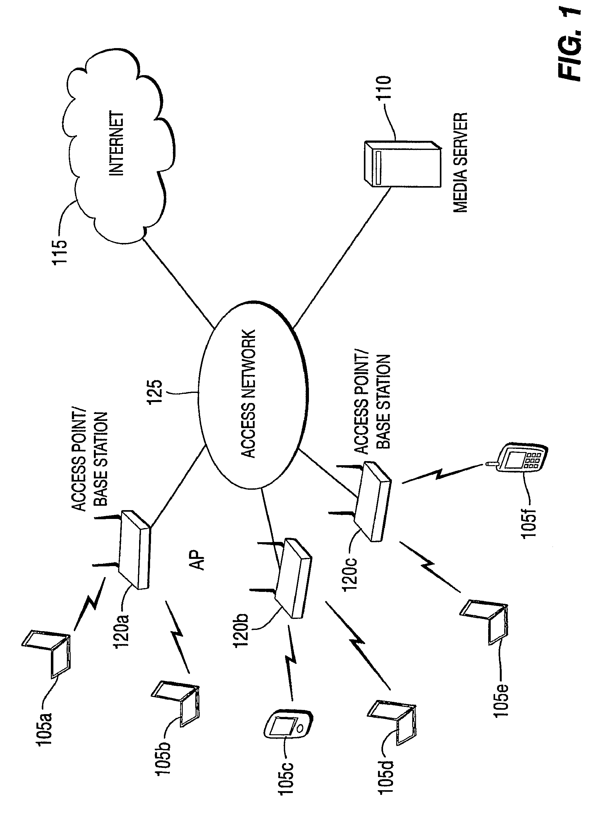
[0016]Referring now to FIG. 1, an exemplary multicast / broadcast video system in accordance with the principles of the present invention is shown. While FIG. 1 depicts wireless devices only, the present invention can be used in wired line or wireless configurations or configurations including both wired line and wireless devices. It is noted that the RTCP control bandwidth in wireless environments is more critical. The wireless devices 105a, 105b, 105c, 105d, 105e and 105f are connected to a video multicast server 110 and the Internet 115 through wireless access points / base stations 120a, 120b and 120c and a high-speed wired access network (e.g. Ethernet) 125. The video server 110 multicasts one or more video programs over the high-speed wired network 125 to the wireless access points / base stations 120a, 120b and 120c. The access points / base stations 120a, 120b and 120c distribute the video to the wireless devices 105a-105f in multicast / broadcast over the wireless links between the w...


PUM


Abstract

A method and apparatus for providing channel condition feedback in a multicast network are described including estimating a indication of channel condition, determining a receiver class based on the estimated indication of channel condition, calculating a delay, delaying transmission of the estimated indication of channel condition for the calculated delay, receiving a report from another receiver in the determined receiver class, the report including an indication of channel condition and canceling the delay if the received indication of channel condition is one of greater than and equal to the estimated indication of channel condition. The method and apparatus further include transmitting a single report for the calculated receiver class to a server including a worst indication of channel condition for the determined receiver class.

Description

[0001]This application claims the benefit, under 35 U.S.C. §365 of International Application PCT / US2007 / 006014, filed 9 Mar. 2007, which was published in accordance with PCT Article 21(2) on 18 Sep. 2008, in English.FIELD OF THE INVENTION[0002]The present invention relates to video multicast and broadcast systems in general, and in particular, to efficient feedback of receiving channel conditions to a server in an adaptive video multicast and broadcast systems.BACKGROUND OF THE INVENTION[0003]In video multicast / broadcast applications, video data are transmitted from the video server to multiple receivers over wired and / or wireless networks. Herein, a “ / ” is used to indicate alternative names for the same or similar components. A multicast system as used herein is a system in which a server transmits the same data to multiple receivers simultaneously, where the receivers form a subset of all the receivers up to and including all of the receivers. A broadcast system is a system in whi...

Claims


Application Information

Patent Timeline
Patent Type & Authority Patents(United States)
IPC IPC(8): H04B7/00
CPCH04L12/1868H04L29/06027H04L47/10H04L47/12H04L47/15H04L47/283H04L47/32H04N21/44209H04N21/6405H04N21/6582H04L65/605H04L65/4076H04L65/608H04L65/80H04L12/189H04L65/765H04L65/611H04L65/65H04L65/1101
Inventor LIU, HANG
Owner INTERDIGITAL CE PATENT HLDG
Why Eureka
Try Eureka