Power unit for power slide apparatus

a technology of power unit and power slide, which is applied in the direction of roofs, doors, wing accessories, etc., can solve the problems of large shaft size, heavy and expensive metal, and unrational design of power unit, so as to reduce the size of power unit, reduce the vibration itself of power unit, and prevent the weight of the base plate from increasing.

Active Publication Date: 2012-12-04
MITSUI KINZOKU ACT
View PDF27 Cites 5 Cited by
  • Summary
  • Abstract
  • Description
  • Claims
  • Application Information

AI Technical Summary

Benefits of technology

[0010]Hence, it is an object of the present invention to provide a power slide apparatus in which an armature and a flange of the power unit are disposed rationally, thereby reducing a power unit in size.
[0011]It is another object of the invention to reduce the vibration itself of the power unit to prevent the base plate from increasing in weight. Thus, in the invention, a difference in weight between power units disposed on both sides of the base plate is reduced, thereby reducing the vibration itself of the power unit.

Problems solved by technology

However, since the armature and the flange are disposed at a position far away from the cable drum, the design of the power unit is not rational, and the power unit is large in size in the axial direction of the drum shaft.
Thus, it is necessary that the drum shaft be formed of heavy and expensive metal.
This fact causes another problem that the cable drum which can be made of resin must be formed as a member that is independent of the drum shaft, the number of parts is increased, the assembling cost is increased, and the assembling precision is deteriorated.
Further, since the conventional power unit has sufficient output for smoothly sliding the slide door, the power unit is heavy, and a metal base plate which supports the heavy power unit is also heavy in structure.
In addition, the heavy power unit is prone to vibrate when a vehicle runs, and this vibration may bring about unexpected metal fatigue in the base plate.
Thus, the conventional base plate is reinforced in many ways, and there is a tendency that the base plate further becomes heavy.

Method used


Image

  • Power unit for power slide apparatus
  • Power unit for power slide apparatus
  • Power unit for power slide apparatus

Examples


Embodiment Construction

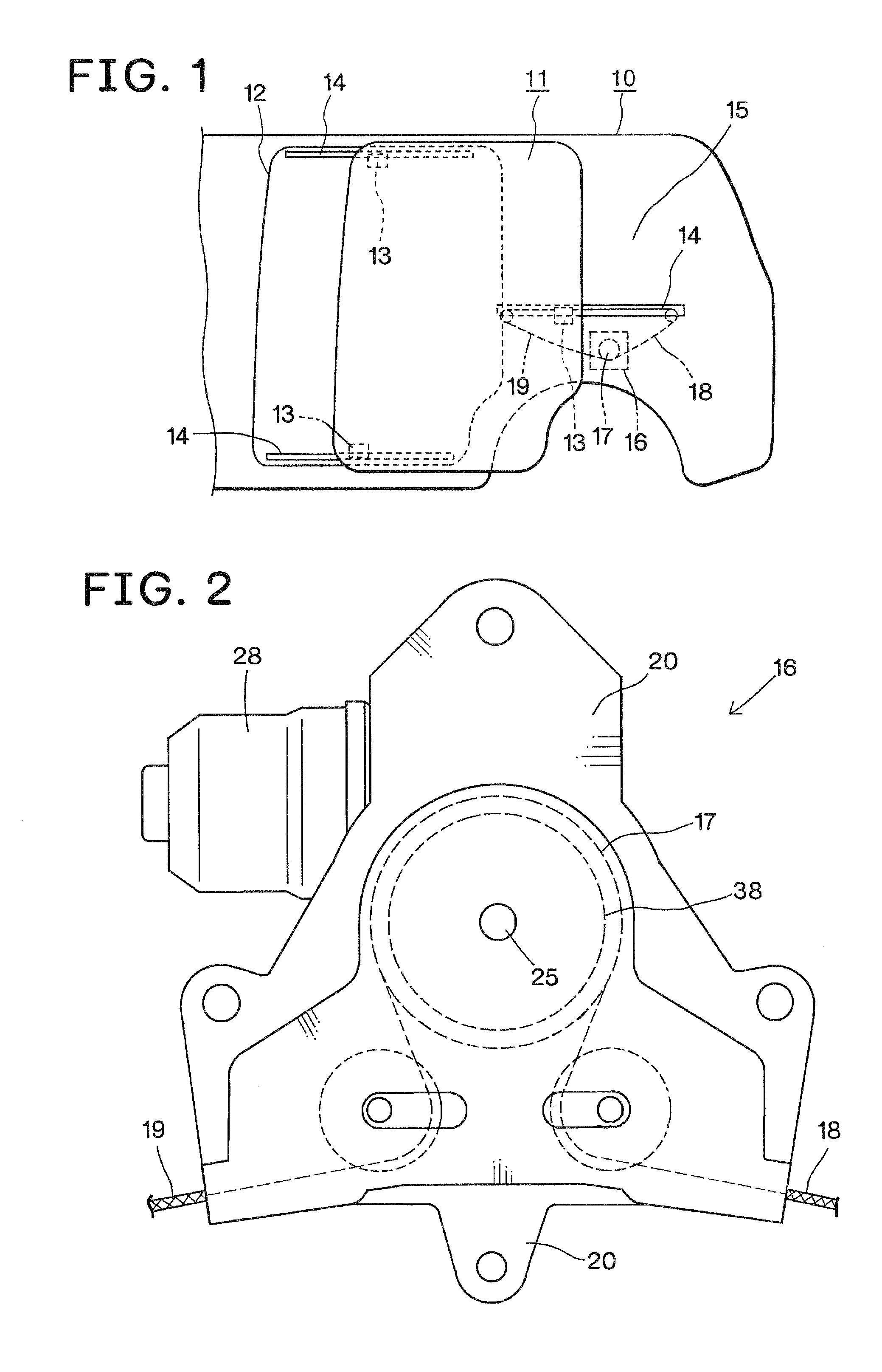
[0016]An embodiment of the present invention will be explained with reference to the drawings. FIG. 1 shows a vehicle body 10, a slide door 11 which is slidably mounted on the vehicle body 10, and a door opening 12 which can be closed with the slide door 11. The slide door 11 is provided with a plurality of guide rollers 13. The vehicle body 10 is provided with a plurality of guide rails 14 which are slidably engaged with the guide rollers 13. The slide door 11 is slidably mounted on the vehicle body 10 by the engagement between the guide rollers 13 and the guide rails 14.

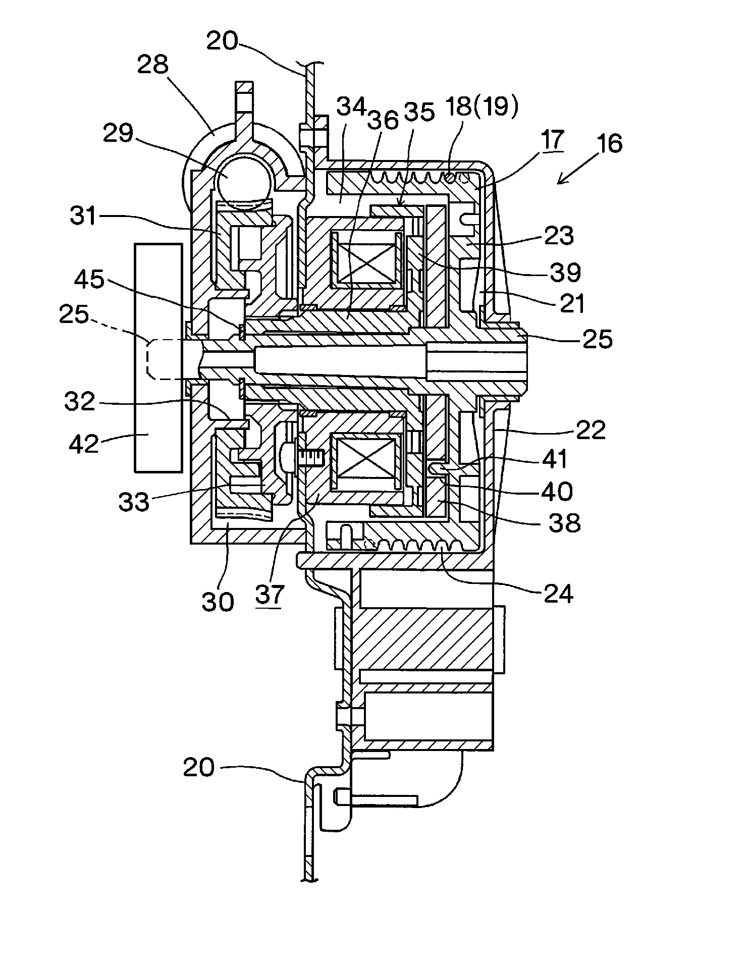
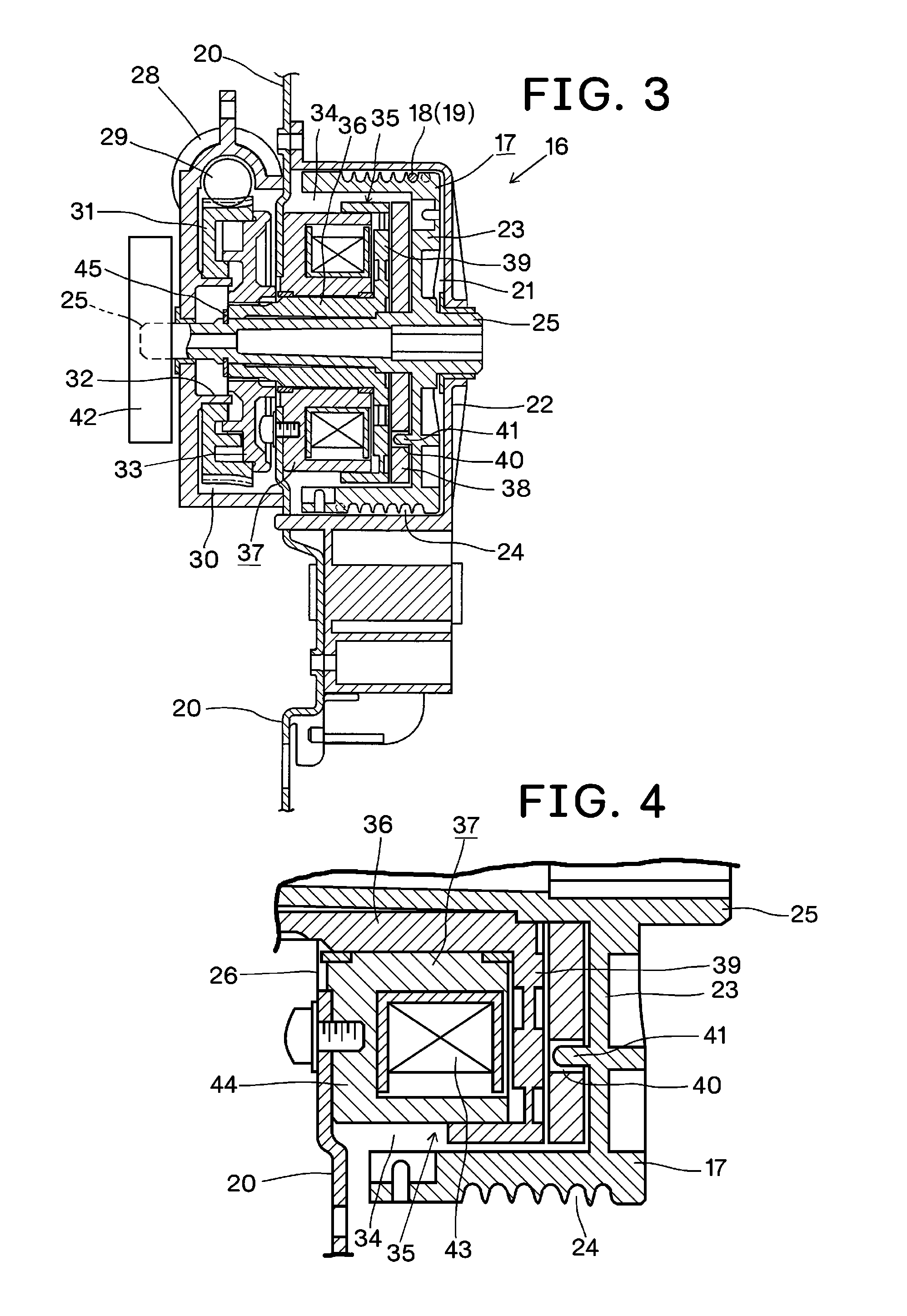
[0017]A power unit 16 of the power slide apparatus is provided in a vehicle inside space of a quarter panel 15 of the vehicle body 10. As shown in FIGS. 2 and 3, the power unit 16 is provided with a cable drum 17, and base ends of a door-opening cable 18 and a door-closing cable 19 are connected to the cable drum 17. Tip ends of the cables 18 and 19 are connected to the slide door 11. When the cable drum 17 rotates...


PUM


Abstract

A power unit 16 includes an armature 38 rotated always in unison with a cable drum 17 and movable in an axial direction of a drum shaft 25, a flange 39 always connected to a motor 28 side, and a magnetic coil portion 37 bringing the armature 38 into abutment against the flange 39. The armature is disposed adjacent to a side of the drum rim body 23 of the cable drum 17, the magnetic coil portion 37 is disposed on the other side of the armature 38, and the flange 39 is disposed between the magnetic coil portion 37 and the armature 38.

Description

TECHNICAL FIELD[0001]The present invention relates to a power slide apparatus for a vehicle slide door, and more particularly, to an improvement of a power unit for the power slide apparatus.BACKGROUND ART[0002]Conventionally, there is a known power unit for a power slide apparatus (see patent documents 1 and 2). The power unit includes a cylindrical cable drum which rotates around a drum shaft by power of a motor and has a door-opening cable and a door-closing cable wound around an outer periphery of the cable drum. The power unit also includes a clutch mechanism which switches between a connection state in which rotation of the motor is transmitted to the cable drum and a non-connection state in which the rotation is not transmitted to the cable drum. In the power unit, when the cable drum rotates in the door-opening direction, the door-opening cable is reeled up around the cable drum, and the door-closing cable is pulled out from the cable drum to slide the slide door in the door...

Claims


Application Information

Patent Timeline
Patent Type & Authority Patents(United States)
IPC IPC(8): E05F11/54
CPCE05F15/646F16D27/112B60J7/0573E05Y2201/246E05Y2201/462E05Y2800/232E05Y2201/216E05F15/603E05Y2900/542
Inventor KITA, SHINICHIROHANAKI, NAOKISHIMURA, RYOJI
Owner MITSUI KINZOKU ACT
Why Eureka
Try Eureka