Piezoelectric element, liquid ejecting head, and liquid ejecting apparatus

a liquid ejecting head and ejecting device technology, applied in the direction of device details, device details, piezoelectric/electrostrictive device details, etc., can solve the problems of piezoelectric body dielectric breakdown, deformation of pressure capacity and other properties of pzt, etc., to improve reliability

Active Publication Date: 2012-12-04
SEIKO EPSON CORP
View PDF1 Cites 8 Cited by
  • Summary
  • Abstract
  • Description
  • Claims
  • Application Information

AI Technical Summary

Benefits of technology

[0009]Under this configuration, positive and negative charges generated in the protective layer travel through the antistatic layer and are neutralized there, leaving a reduced number of charges in the protective layer. This prevents dielectric breakdowns from occurring in the piezoelectric body.
[0018]Under this configuration, which includes the use of the liquid ejecting head and piezoelectric element, the liquid ejecting apparatus is protected from dielectric breakdowns due to electrification and thus offers improved reliability.

Problems solved by technology

However, ink, water (moisture), and other external factors often degrade the pressure capacity and other properties of PZT.
However, such a highly insulating protective layer usually has a high dielectric constant and thus is easily electrified.
If electrified, the protective layer may cause a dielectric breakdown of the piezoelectric body adjacent thereto.

Method used


Image

  • Piezoelectric element, liquid ejecting head, and liquid ejecting apparatus
  • Piezoelectric element, liquid ejecting head, and liquid ejecting apparatus
  • Piezoelectric element, liquid ejecting head, and liquid ejecting apparatus

Examples


embodiment 1

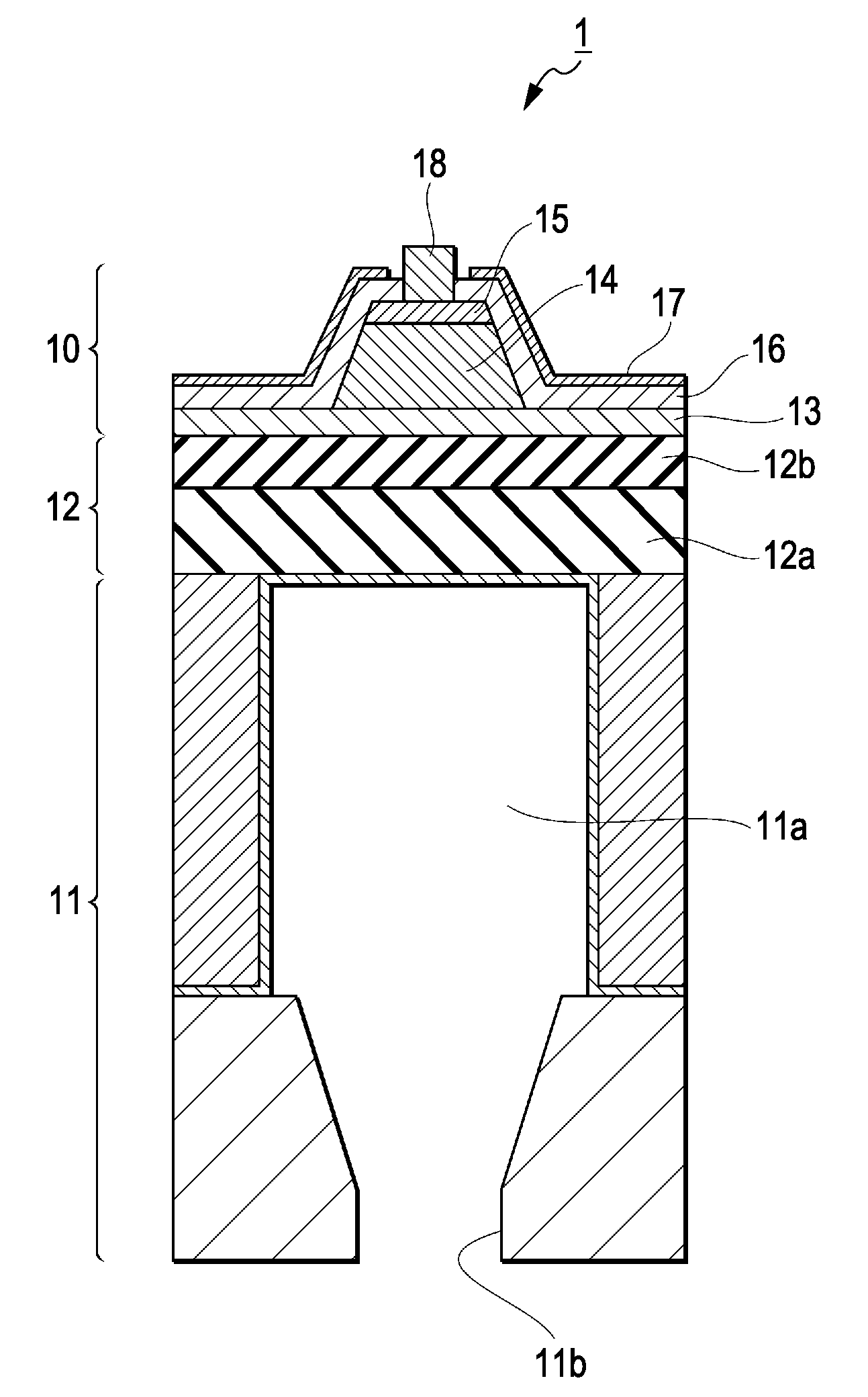
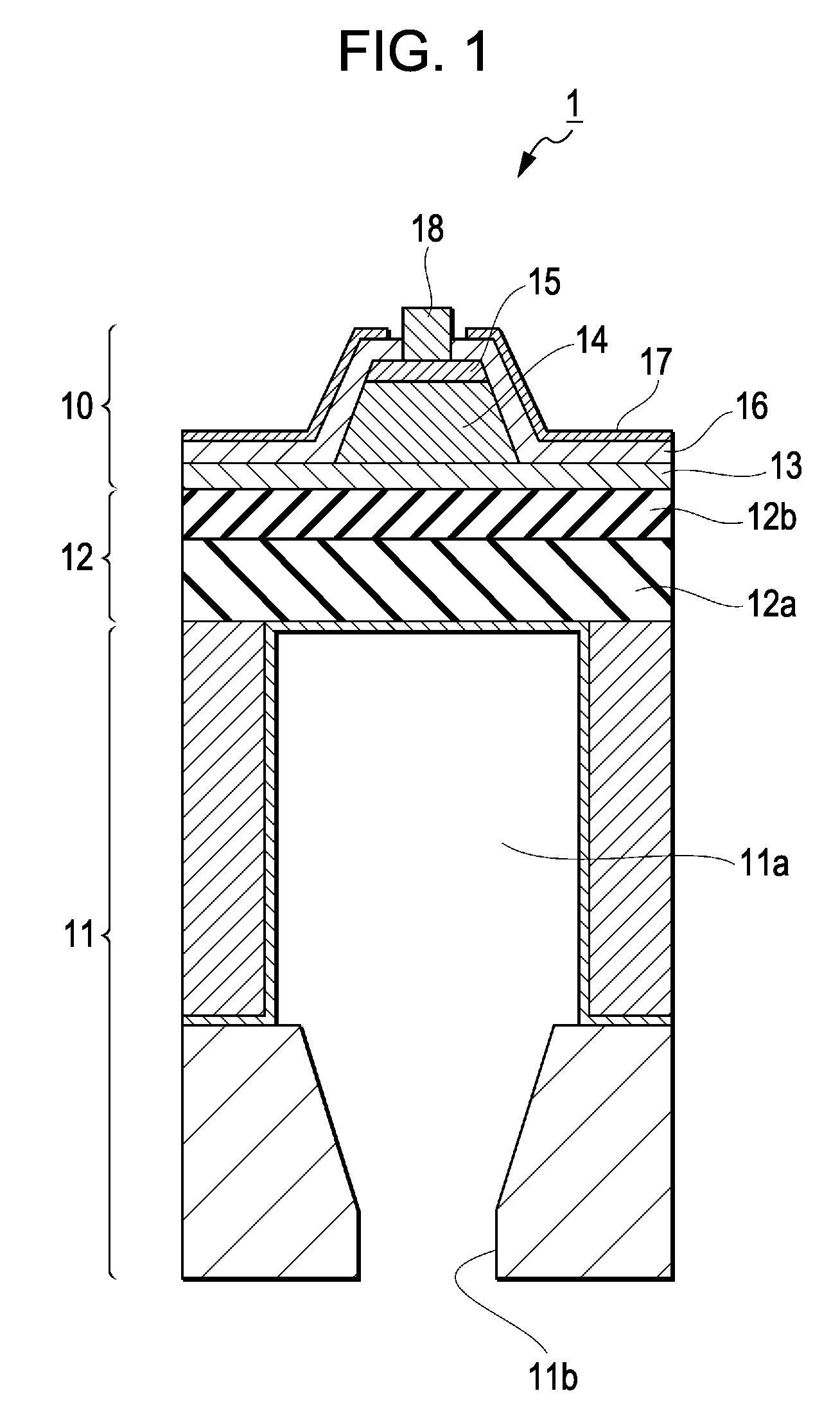
[0027]FIG. 1 illustrates a configuration of a liquid ejecting head having a piezoelectric element according to the invention. As shown in this drawing, the liquid ejecting head 1 has a substrate 11 having a hollow and a nozzle for ink, an elastic layer (diaphragm) 12 formed on the substrate 11, a lower electrode 13, a piezoelectric body 14 formed on the lower electrode 13, an upper electrode 15 formed on the piezoelectric body 14, a protective layer 16 covering the sides of the piezoelectric body 14 and the top of the upper electrode 15 to shield the piezoelectric body 14 from water and other contaminants, an antistatic layer 17 formed on the protective layer to prevent the protective layer 16 from being electrified, and some other components.

[0028]The lower electrode 13, piezoelectric body 14, upper electrode 15, protective layer 16, antistatic layer 17, and some other components compose a piezoelectric element 10. The upper electrode 15 is in contact with a lead wire 18.

[0029]The ...

embodiment 2

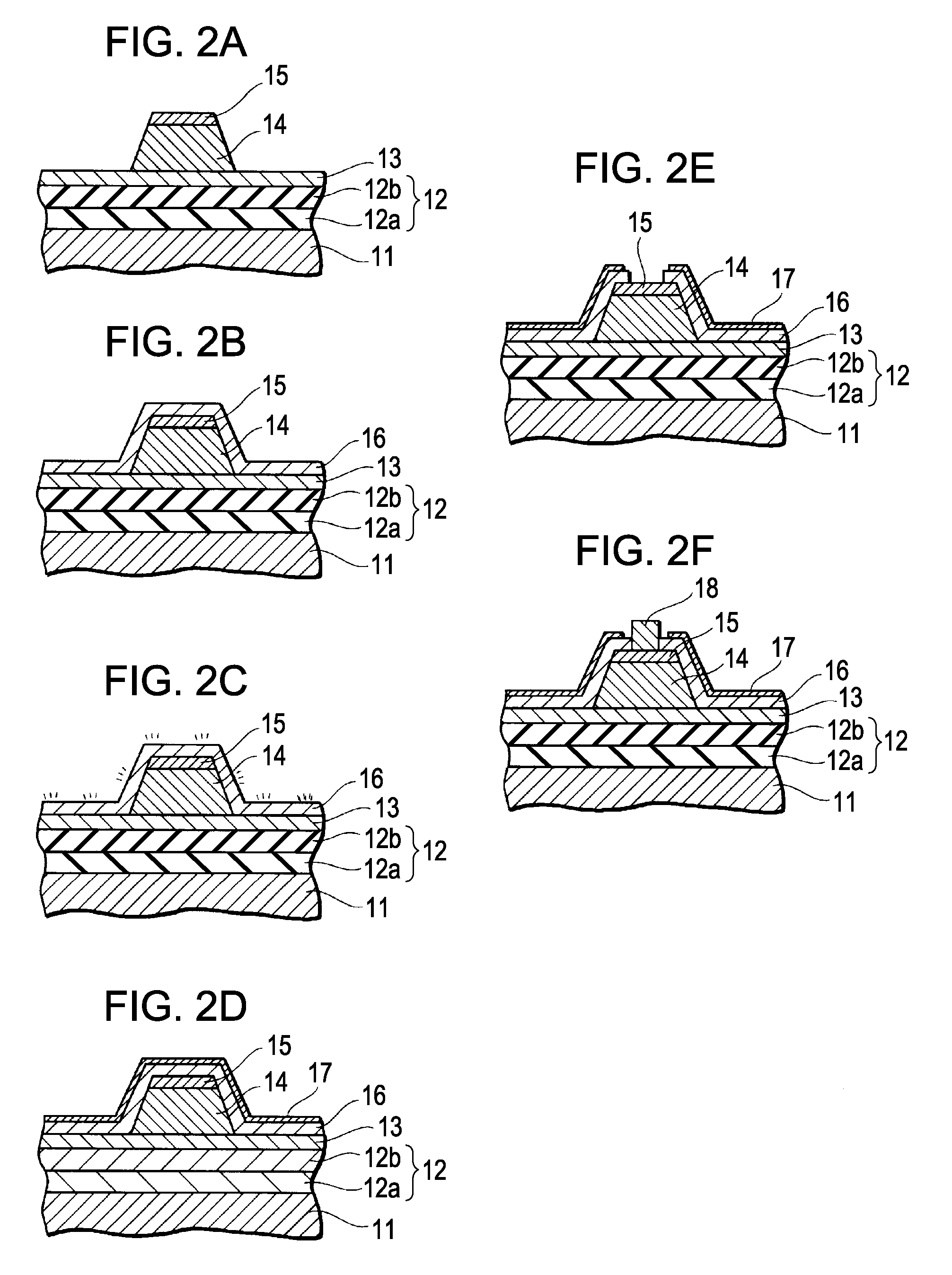
[0039]The following describes a method for manufacturing a piezoelectric element (liquid ejecting head) according to Embodiment 1, which has a protective layer and an antistatic layer covering it, with reference to FIGS. 2A to 2F.

[0040](1) Forming a Piezoelectric Element

[0041]First, the structure shown in FIG. 2A is formed in the following way. One of the surfaces of a substrate 11, which is made of silicon single crystals or some other material, is oxidized by heating so that a silicon-dioxide-based elastic layer 12a can be formed with a thickness in the range of 1 to 2 μm. Then, an insulating layer 12b is formed, using zirconium oxide (ZrO2) or some other material, with a thickness of about 0.4 μm on the elastic layer 12a. Then, platinum (Pt) or some other material is deposited by sputtering, vapor deposition, or some other method on the insulating layer 12b until the thickness reaches about 200 nm, yielding a lower electrode 13. Then, the lower electrode 13 is formed into a desir...

embodiment 3

[0068]In a liquid ejecting head according to Embodiment 3, an antistatic layer is formed in a protective layer.

[0069]FIG. 4 illustrates a configuration of a liquid ejecting head having a piezoelectric element according to the invention. The numerals are defined the same as those in FIG. 1.

[0070]The liquid ejecting head 1 has a substrate 11 having a pressure chamber 11a and a nozzle 11b for ink, an elastic layer (diaphragm) 12 formed on the substrate 11, a lower electrode 13, a piezoelectric body 14 formed on the lower electrode 13, an upper electrode 15 formed on the piezoelectric body 14, a lower protective layer 16 covering the sides of the piezoelectric body 14 and the top of the upper electrode 15 to shield the piezoelectric body 14 from water and other contaminants, an antistatic layer 17 formed on the lower protective layer 16 to prevent the lower protective layer 16 from being electrified, an upper protective layer 19 formed on the antistatic layer 17, a lead wire 18, and som...


PUM


Abstract

A piezoelectric element has a piezoelectric body, two electrodes sandwiching the piezoelectric body, a protective layer covering the piezoelectric body and the two electrodes, and an antistatic layer formed on and / or in the protective layer.

Description

BACKGROUND[0001]1. Technical Field[0002]The present invention relates to a piezoelectric element, a liquid ejecting head, and a liquid ejecting apparatus and particularly relates to a piezoelectric element, a liquid ejecting head, and a liquid ejecting apparatus that are free from electrification-induced dielectric breakdowns of the piezoelectric body contained therein.[0003]2. Related Art[0004]Piezoelectric elements are stretched or contracted on application of voltage, and their use includes the source of driving force for diaphragms and actuators for liquid ejecting heads (ink jet heads).[0005]Piezoelectric elements for liquid ejecting heads, which require fine patterning, are made of a ferroelectric piezoelectric material, such as PZT (lead zirconate titanate). However, ink, water (moisture), and other external factors often degrade the pressure capacity and other properties of PZT. As a solution to this problem, JP-A-2005-178293 has proposed covering a piezoelectric element wit...

Claims


Application Information

Patent Timeline
Patent Type & Authority Patents(United States)
IPC IPC(8): B41J2/045
CPCB41J2/14233B41J2/161B41J2/1626B41J2/1631B41J2/1642B41J2/1645B41J2/1646H01L41/04H10N30/883H10N30/2047H10N30/80
Inventor TAKAKUWA, ATSUSHI
Owner SEIKO EPSON CORP
Why Eureka
Try Eureka