Centrifugal separator with venturi arrangement

a centrifugal separator and venturi technology, applied in centrifuges and other directions, can solve the problems of hindering drainage and other problems, and achieve the effect of compact structure and reduced complexity

a centrifugal separator and venturi technology, applied in centrifuges and other directions, can solve the problems of hindering drainage and other problems, and achieve the effect of compact structure and reduced complexity

US8323168B2Inactive Publication Date: 2012-12-04MANN HUMMEL GMBH

Image

  • Centrifugal separator with venturi arrangement
  • Centrifugal separator with venturi arrangement
  • Centrifugal separator with venturi arrangement

Examples


Embodiment Construction

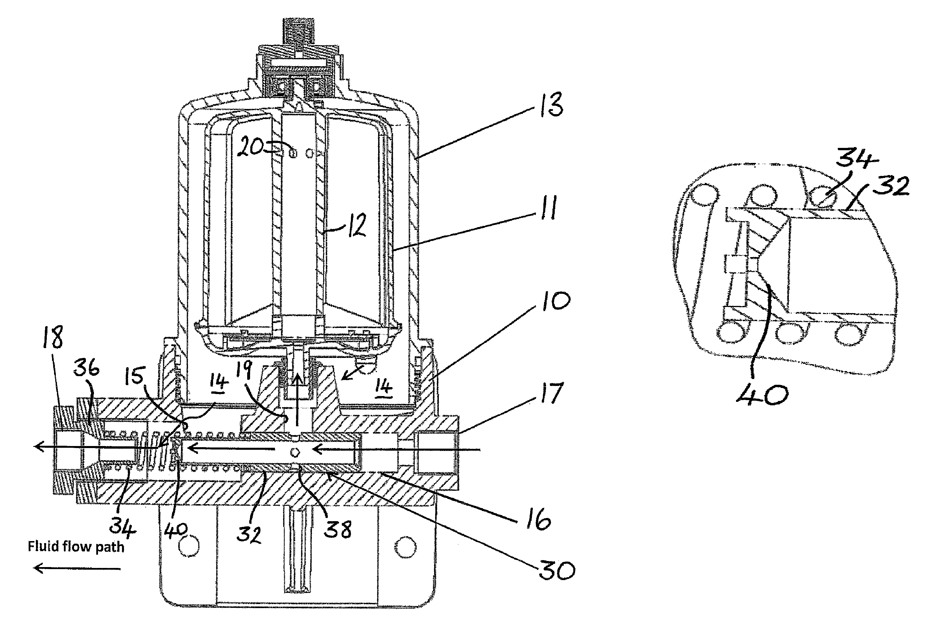
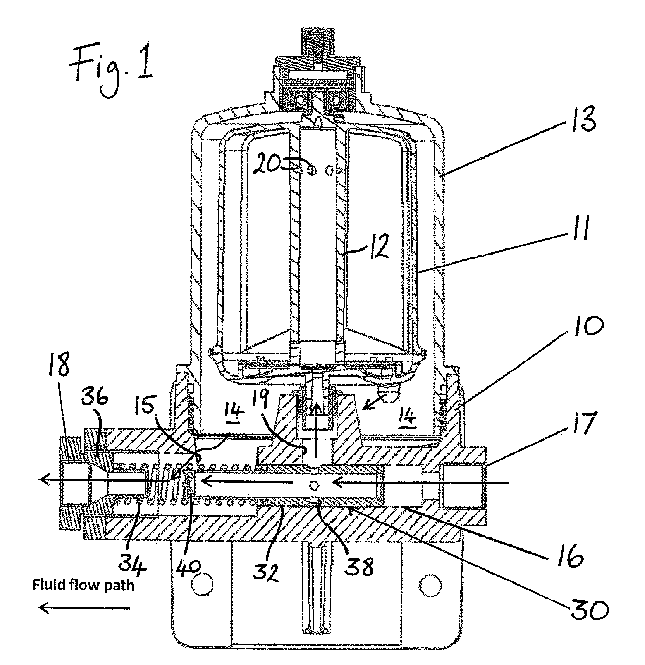
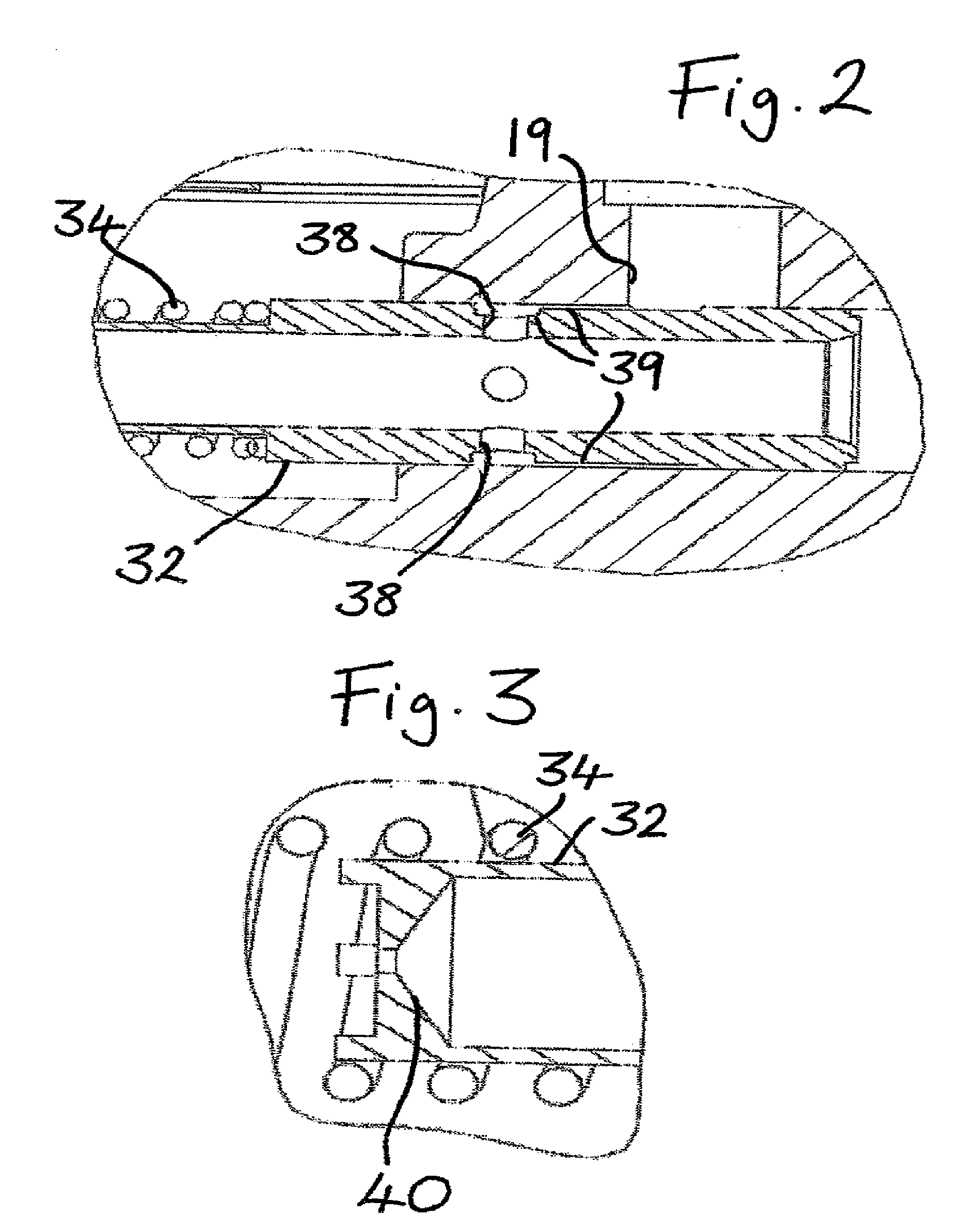
[0025]Referring firstly to FIG. 1, this embodiment has the typical features of a self-powered centrifugal separator, namely a base 10, a rotor 11 mounted on a substantially vertical axis 12 for rotation thereabout, a housing 13 mounted on the base 10 and enclosing the rotor 11, and a sump 14 formed in the base 10 below the rotor 11. A fluid passageway 16 extends through the base 10 from an inlet port 17 to an outlet port 18. This fluid passageway 16 is arranged to supply fluid, through a diversion port 19, to the interior of the rotor 11 by way of the rotation axis 12. The fluid enters the rotor interior through apertures 20 in an upper region of the axis 12 and exits through tangentially directed nozzles (not shown) at the bottom of the rotor, reaction to which serves to spin the rotor 10 about its axis. Fluid from the nozzles drains into the sump 14. A drainage passage 15 connects the sump 14 to the passageway 16 for return, via the outlet port 18, to a system fluid reservoir (not...


PUM


Abstract

The invention describes a self-powered centrifugal separator comprising a base, a rotor mounted on an operably substantially vertical axis for rotation thereabout by reaction to fluid emission from rotor nozzles therein, a housing mounted on the base and enclosing the rotor, a sump formed in the base below the rotor, a fluid passageway through the base extending from an inlet port to an outlet port and including a diversion port to supply fluid to the interior of the rotor by way of the rotation axis, a drain passage in the base for draining fluid from the sump to the fluid passageway, and a venturi arrangement provided in the fluid passageway in the base to develop suction pressure to draw fluid from the drainage passage into the fluid passageway, whereas a spring loaded valve body is provided in the fluid passageway, said body being configured and arranged to shut off supply of fluid to the interior of the rotor when pressure of fluid entering the inlet port falls below a predetermined minimum pressure value and also to restrict and / or shut off supply of fluid to the interior of the rotor when pressure of fluid entering the inlet port rises above a second predetermined pressure value.

Description

CROSS REFERENCE TO RELATED APPLICATIONS[0001]This application is US National Stage Entry of international patent application no. PCT / EP2009 / 065052, filed Nov. 12, 2009 designating the United States of America. Priority is claimed based on United Kingdom patent application no. GB 0820868.8, filed Nov. 14, 2008, the entire disclosure of which is incorporated herein by reference.TECHNICAL FIELD[0002]This invention concerns improvements to a fluid-powered centrifugal separator of the type which incorporates a venturi arrangement.BACKGROUND OF THE INVENTION[0003]Fluid-powered centrifugal separators are well known for separating fluids of different densities or for separating particulate matter from liquids and have long been used in lubrication systems for engines, particularly diesel-powered vehicle engines, as well as in other industrial separation processes.[0004]The principle of operation of such a centrifugal separator is that a housing contains a rotor which is supported therein to...

Claims


Application Information

Patent Timeline
04 Dec 2012
Publication
US8323168B2
IPC
B04B9/06
CPC
B04B11/04; B04B5/005; B04B5/12; B04B9/06; B04B11/02; B04B5/00; B04B7/00; B04B7/02
Inventors
NAEGELEN, SEBASTIAN; DWORATZEK, KLEMENS