
Method for manufacturing a surgical saw blade with a blade head and raised boss around which the blade head pivots

a manufacturing method and technology of applied in the field of manufacturing a surgical saw blade, can solve the problems of reducing the extent to which the material forming the guide becomes so worn, and reducing the extent of material deformation

Active Publication Date: 2012-12-04
STRYKER EURO OPERATIONS HLDG LLC
View PDF14 Cites 16 Cited by
  • Summary
  • Abstract
  • Description
  • Claims
  • Application Information

AI Technical Summary

Benefits of technology

The invention is about a new way to make a saw blade that can oscillate. The method involves making a pivot boss in a plate, then welding the plates together to form the blade bar. This process minimizes deformation of the plates and reduces the bowing of the blade bar. The result is a more precise and accurate saw blade.

Problems solved by technology

When a conventional blade is actuated, the oscillating movement of the blade imposes significant wear on the surfaces of the cutting guide defining the slot in which the blade is seated.
Further, use of the oscillating tip blade reduces the extent to which the material forming the guide becomes so worn that the guide itself is rendered useless.
This is because surface rough spots will result in wear being concentrated around these points and the complementary surfaces of the blade head that bear against these surfaces.
This wear can induce failure in one or both of these components.
Even if this wear does not induce structure failure, it can cause an appreciable amount of friction-induced heat to be generated.
Forming the blade bar using this process can be so expensive that it can be economically impracticable to provide an oscillating tip saw blade.
Such curving of the blade can, in turn, result in the blade cutting the tissue along a path that deviates from the intended cut path.
This curvature can potentially be so great that it adversely affects the ability of the blade to travel in the slotted cutting guide in which it is inserted.

Method used


Image

  • Method for manufacturing a surgical saw blade with a blade head and raised boss around which the blade head pivots
  • Method for manufacturing a surgical saw blade with a blade head and raised boss around which the blade head pivots
  • Method for manufacturing a surgical saw blade with a blade head and raised boss around which the blade head pivots

Examples


Embodiment Construction

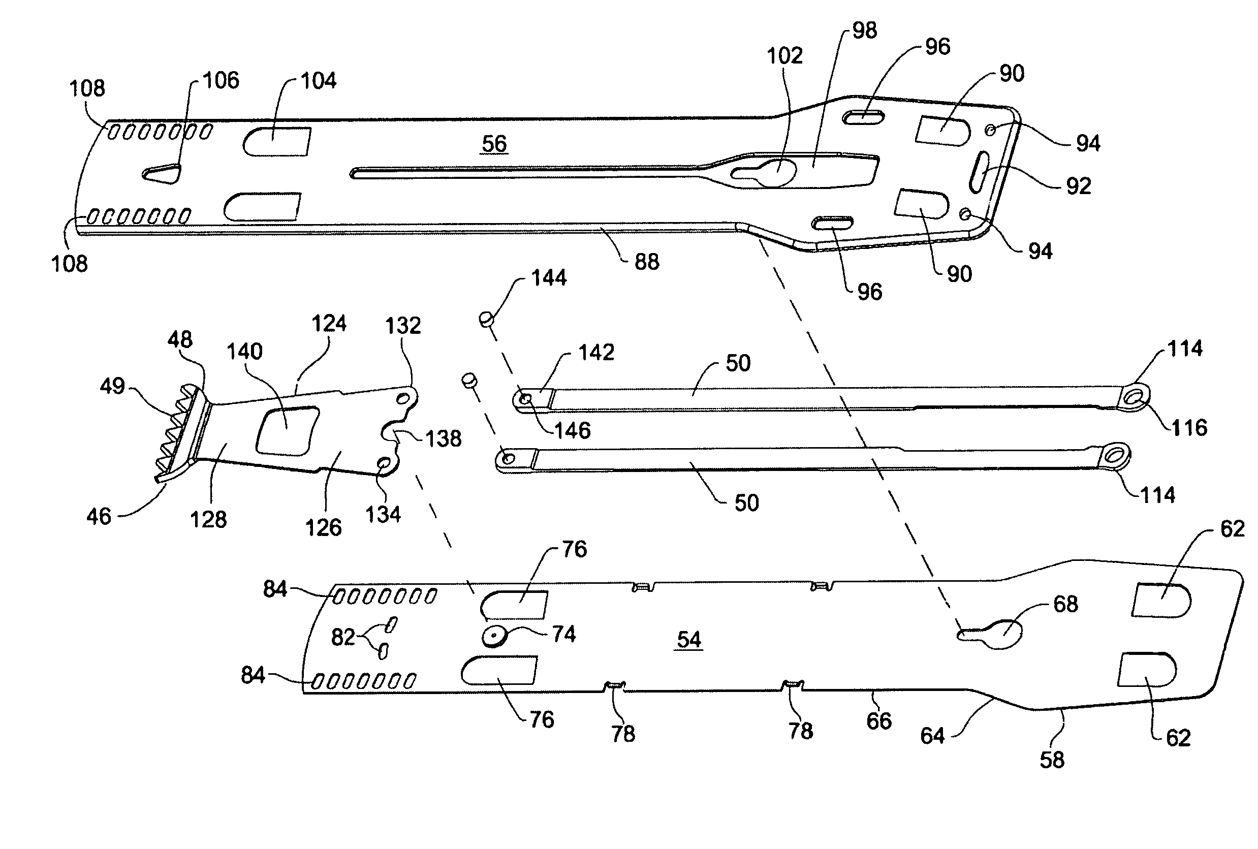
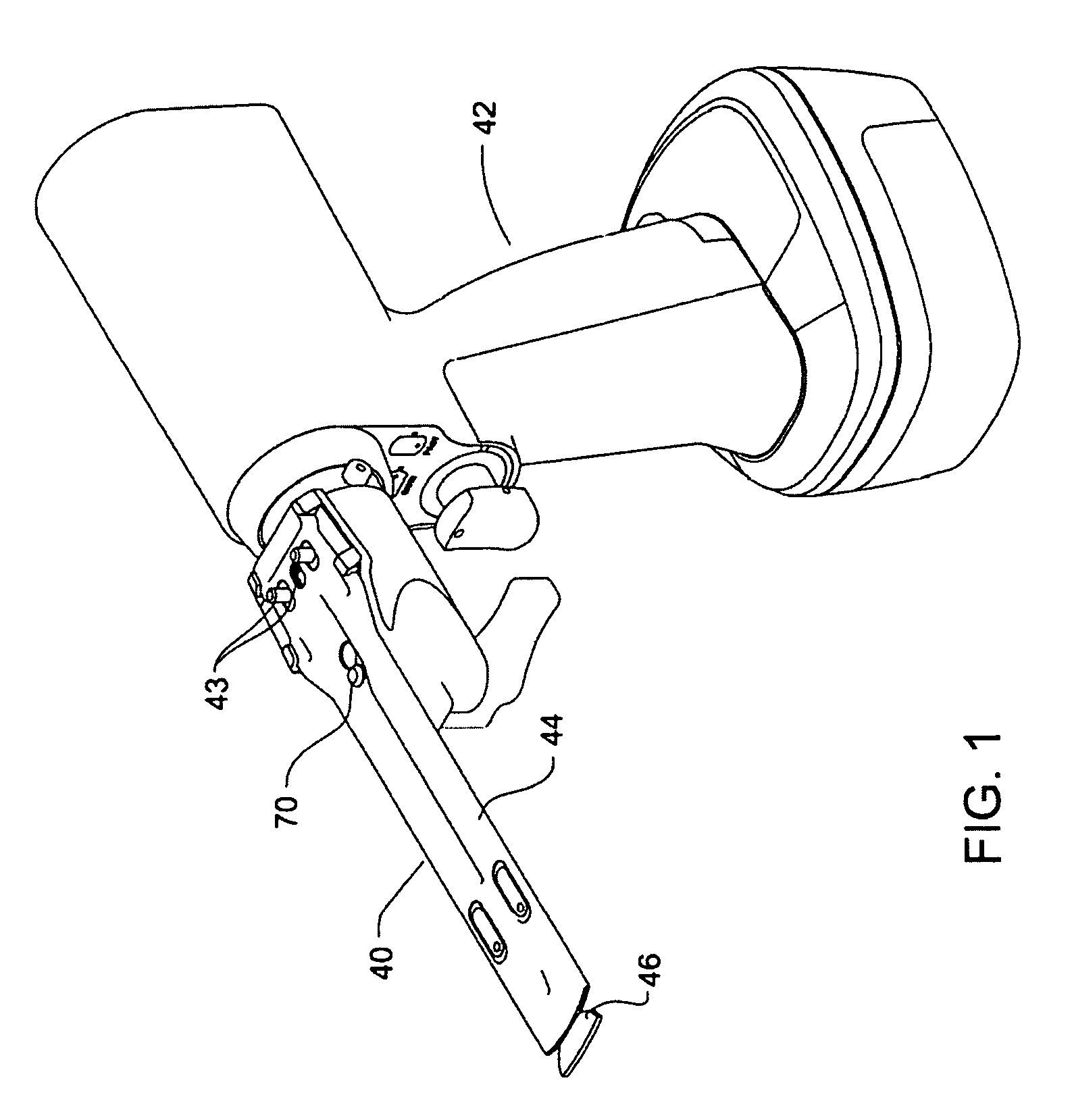
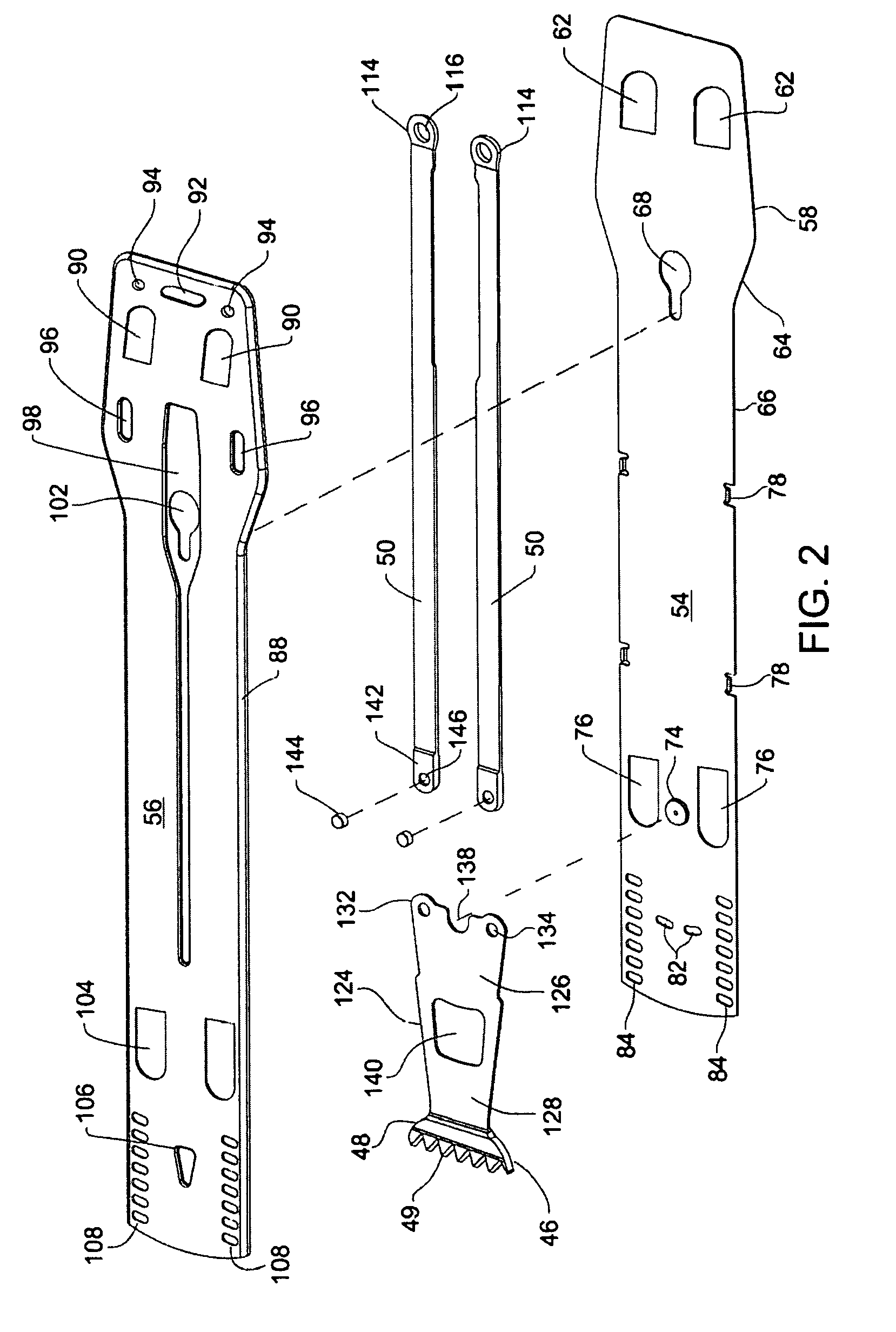
[0037]FIGS. 1 and 2 depict a saw blade assembly 40 constructed in accordance with this invention attached to a handpiece 42. Saw blade assembly 40 includes a blade bar 44 that is removably attached to the distal end of the handpiece 42. (“Distal” means away from the surgeon, i.e., towards the surgical site to which the assembly is applied. “Proximal” means towards the surgeon, i.e., away from the surgical site.) A blade head 46 is disposed in and pivotally mounted to the blade bar 44. The blade head 46 has a crown 48 located forward of the blade bar 44. The crown 48 is formed with cutting teeth 49. Drive rods 50 disposed in the blade bar 44 extend proximally rearward from the blade head 46. Drive rods 50 are releaseably connected to an oscillating drive mechanism, internal to the handpiece (drive mechanism not illustrated and not part of this invention). As a consequence of the actuation of the drive mechanism, the drive rods 50 reciprocate back and forth along the longitudinal axis...


PUM

PropertyMeasurementUnit
thicknessaaaaaaaaaa
thicknessaaaaaaaaaa
thicknessaaaaaaaaaa

Abstract

In a method of assembling a surgical saw blade assembly with an blade bar that contains an oscillating head, the blade bar is formed from opposed plates. One of the plates is punch stamped to define a boss around which blade head pivots. The plates are secured to one another in a series of steps in which spaced apart sections of the plates are welded together.

Description

CROSS-REFERENCE TO RELATED APPLICATIONS[0001]This application is a continuation application of PCT Application No. PCT / US2007 / 076321, filed 20 Aug. 2007, which claims priority to U.S. Provisional Patent Application No. 60 / 839,051, filed 21 Aug. 2006, both of which are hereby incorporated by reference in their entireties.FIELD OF THE INVENTION[0002]This invention relates generally to a method of manufacturing a surgical saw blade that has static blade bar and a head that pivots relative to the blade bar.BACKGROUND OF THE INVENTION[0003]A sagittal saw blade is a surgical saw with a head that pivots around an axis that is perpendicular to the blade. The United States patent application entitled SURGICAL SAGITTAL SAW WITH INDEXING HEAD AND TOOLLESS BLADE COUPLING ASSEMBLY FOR ACTUATING AN OSCILLATING TIP SAW BLADE AND OSCILLATING TIP SAW BLADE WITH SELF CLEANING HEAD filed 16 Aug. 2006, U.S. Patent Pub. No. US 2007 / 0119055 A1, the contents of which are incorporated herein by reference, ...

Claims


Application Information

Patent Timeline
Patent Type & Authority Patents(United States)
IPC IPC(8): A61B17/00B23P11/00
CPCA61B17/14A61B17/148A61B17/141Y10T29/49826A61B2017/00526A61B17/142
Inventor WALEN, JAMES G.COSGROVE, LIAMBRINDLEY, ROBERT
Owner STRYKER EURO OPERATIONS HLDG LLC
Features
  • Generate Ideas
  • Intellectual Property
  • Life Sciences
  • Materials
  • Tech Scout
  • Unparalleled Data Quality
  • Higher Quality Content
  • 60% Fewer Hallucinations
Learn More