Filter assembly for computed tomography systems

a computed tomography and filter technology, applied in the field of computed tomography, can solve the problems of difficult movement of the attenuation filter relative to a stationary workpiece in the collimator, severe image artefacts, and brittleness, and achieve the effect of improving performan

Inactive Publication Date: 2012-12-04
KONINK PHILIPS ELECTRONICS NV
View PDF15 Cites 6 Cited by
  • Summary
  • Abstract
  • Description
  • Claims
  • Application Information

AI Technical Summary

Benefits of technology

[0013]By shaping the filter element and the first support plate with a through-notch in the center of the filter assembly along a direction perpendicular to the projection axis, other collimator parts, for example, a sensor, can be easily placed in the space left vacant by the notches. The position of the sensor or the filter assembly can be easily fixed by relative motion between them, without blocking.
[0016]When, in operation, a filter element breaks down and when more than one filter element is used in a filter assembly, it is possible to replace the defective filter element in the filter assembly with a new one in the field by moving the filter assembly along the direction perpendicular to the projection axis so as to place the new filter element in the right position.

Problems solved by technology

The x-rays may degrade the polymer, causing it to become brittle.
In combination with mechanical stresses, this can cause cracks which introduce discontinuity of the x-ray beams and may thus cause severe image artefacts.
Intactness of the supporting wall will stop any workpiece from moving through the saddle notch and make movement of the attenuation filter relative to a stationary workpiece in a collimator difficult.
Furthermore, the solution provided in the prior art cannot combat the crack introduced by centrifugal forces, which is known as a large source of mechanical stress causing cracks in the attenuation filter.

Method used


Image

  • Filter assembly for computed tomography systems
  • Filter assembly for computed tomography systems
  • Filter assembly for computed tomography systems

Examples


Embodiment Construction

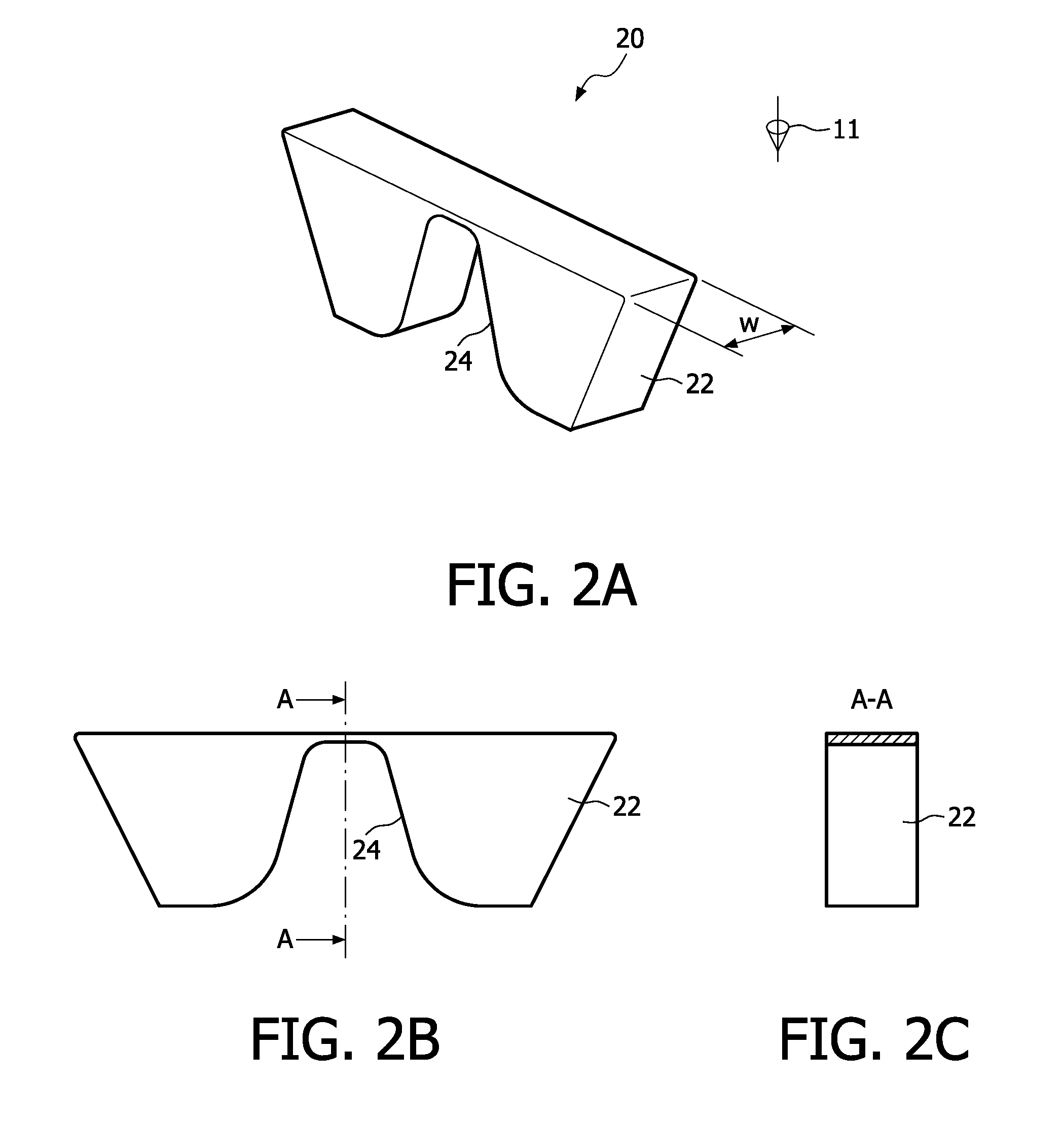
[0029]FIG. 2A is a diagram of an embodiment of an attenuation filter 20 according to the invention; FIGS. 2B and 2C are a corresponding schematic front view and a cross-sectional view, respectively, taken on the A-A axis. The attenuation filter 20 comprises a filter block 22, made of, for example, Teflon. It will be evident to those skilled in the art that other similar materials may be used for the attenuation filter 20. Furthermore, the filter block 22 may have any other shape instead of a rectangular shape, for example, the saddle shape as shown in FIG. 2A.

[0030]The filter block 22 has a saddle-notch shape 24. Unlike the saddle notch 14 in FIG. 1A, the saddle notch 24 is shaped in the full width of the filter block 22 without leaving a supporting wall intact. This means that the saddle notch 24 may allow a workpiece to move through the saddle notch from one to the other side of the attenuation filter 20, or may allow the attenuation filter 20 to freely move relative to a stationa...


PUM


Abstract

The invention relates to x-ray filters in a collimator for controlling the energy of an x-ray beam along a projection axis in computed tomography systems. According to the invention, the filter assembly comprises a filter element for attenuating the x-ray beam, and at least a support plate which fixes the filter element. The filter element and the support plate are notch-shaped in the center part of the filter assembly along a direction perpendicular to the projection axis. The design may free space to be used by other collimator parts and further allows use of more than one filter element in a filter assembly for backup purposes. This simplifies replacement of a defective x-ray filter in the field.

Description

FIELD OF THE INVENTION[0001]The invention relates to computed tomography, particularly to x-ray filters for controlling the energy of an x-ray beam in computed tomography systems.BACKGROUND OF THE INVENTION[0002]Computed tomography (CT) systems typically include an x-ray source collimated to form a fan beam directed through an object to be imaged, i.e. a patient, and received by an x-ray detector array. The x-ray source, the fan beam and the detector array are oriented to be situated within the x-y plane of a Cartesian coordinate system, termed the “imaging plane”. The x-ray source and the detector array may be rotated together on a gantry within the imaging plane, around the imaged object, and hence around the z-axis of the Cartesian coordinate system.[0003]In computed tomography systems, a device called collimator is generally used to minimize the x-ray radiation dose a patient receives. One of the ways to achieve this goal is to insert a bowtie-shaped piece of polymer, called “we...

Claims


Application Information

Patent Timeline
Patent Type & Authority Patents(United States)
IPC IPC(8): G21K3/00
CPCA61B6/032G21K1/10A61B6/4035
Inventor LOOS, MARINUS ANTONIUS DIMPHNA MARIAPEETERS, FELIX GODFRIED PETER
Owner KONINK PHILIPS ELECTRONICS NV
Why Eureka
Try Eureka