
Multi-valve cartridge pressure regulator

a pressure regulator and multi-valve technology, applied in the direction of fluid pressure control, process and machine control, instruments, etc., can solve the problems of high cost, difficult installation and maintenance, complex system types, etc., and achieve high level of precision, enhanced flow capacity, and expandable flow capacity

Inactive Publication Date: 2012-12-11
RELIANCE WORLDWIDE CORP
View PDF8 Cites 26 Cited by
  • Summary
  • Abstract
  • Description
  • Claims
  • Application Information

AI Technical Summary

Benefits of technology

[0009]An advantage of the present invention is flow capacity enhanced though specific alignment of the valve cartridges.
[0010]Another advantage is flow control accuracy through independent pressure adjustment of a plurality of valve cartridges.
[0011]Another advantage is flow capacity expandability by the use of valve cartridge plugs which can be fitted in place of valve cartridges to limit flow and allow for future flow expandability.
[0012]Another advantage is the use of multiple valve cartridges which allows for each valve to be adjusted to regulate pressure independently and open or close sequentially, dependent upon the immediate flow requirement.
[0013]Another advantage is that the independently adjustable valve cartridges allow the pressure regulator to control the flow of water with a high level of precision, offering superior durability with little required maintenance.
[0014]Another advantage is that variations in inlet pressure do not affect regulated outlet pressure as long as inlet pressure remains greater than the set pressure.

Problems solved by technology

In some cases is it desirable to have a plurality of pressure regulating valves in parallel or in series in order to convey the required flow capacity with reasonably accurate pressure regulation, but this type of system may be complex, expensive and difficult to install and maintain.

Method used


Image

  • Multi-valve cartridge pressure regulator
  • Multi-valve cartridge pressure regulator
  • Multi-valve cartridge pressure regulator

Examples


Embodiment Construction

[0023]While the following description details the preferred embodiments of the present invention, it is to be understood that the invention is not limited in its application to the details of construction and arrangement of the parts illustrated in the accompanying drawings, since the invention is capable of other embodiments and of being practiced in various ways.

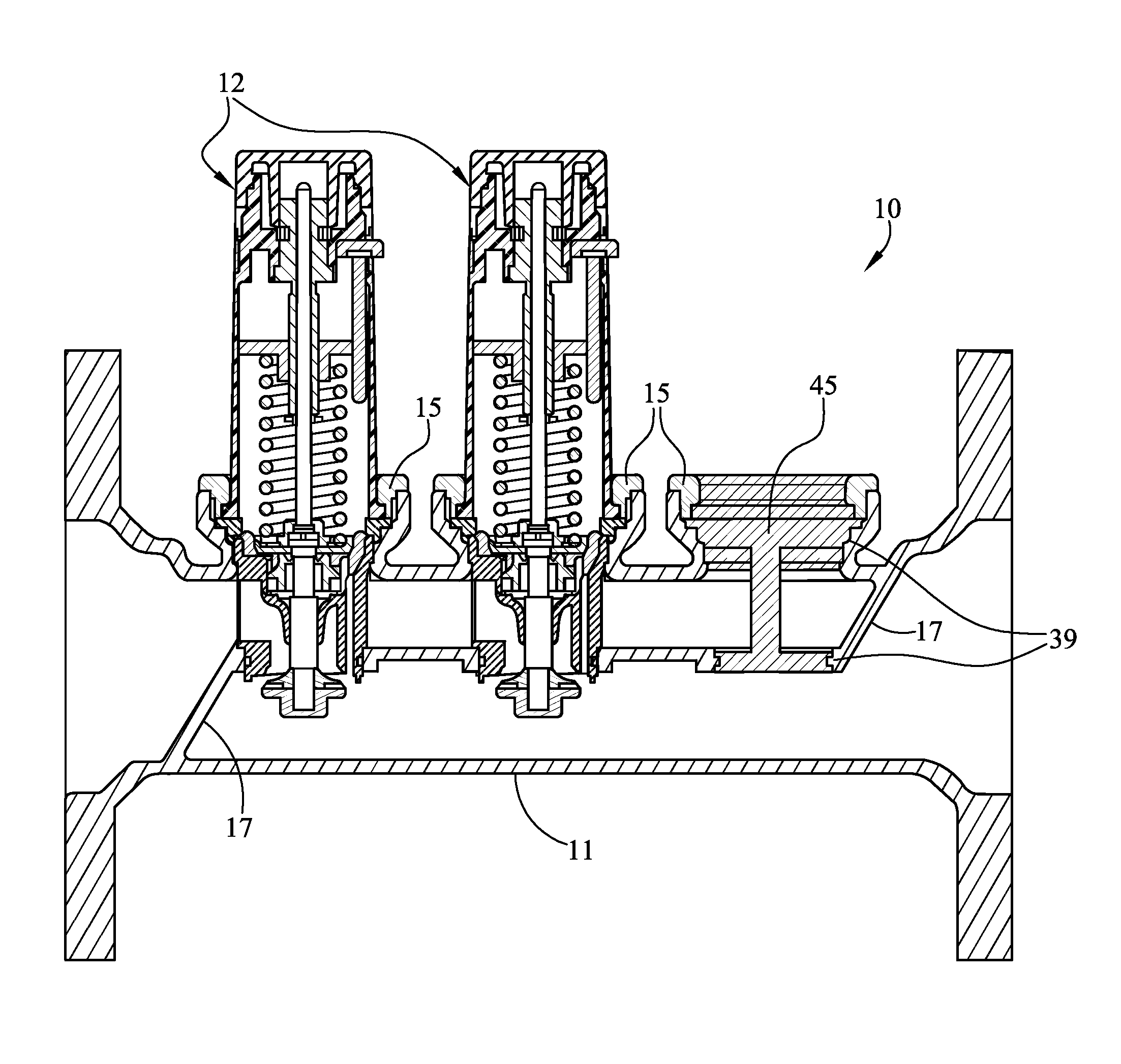
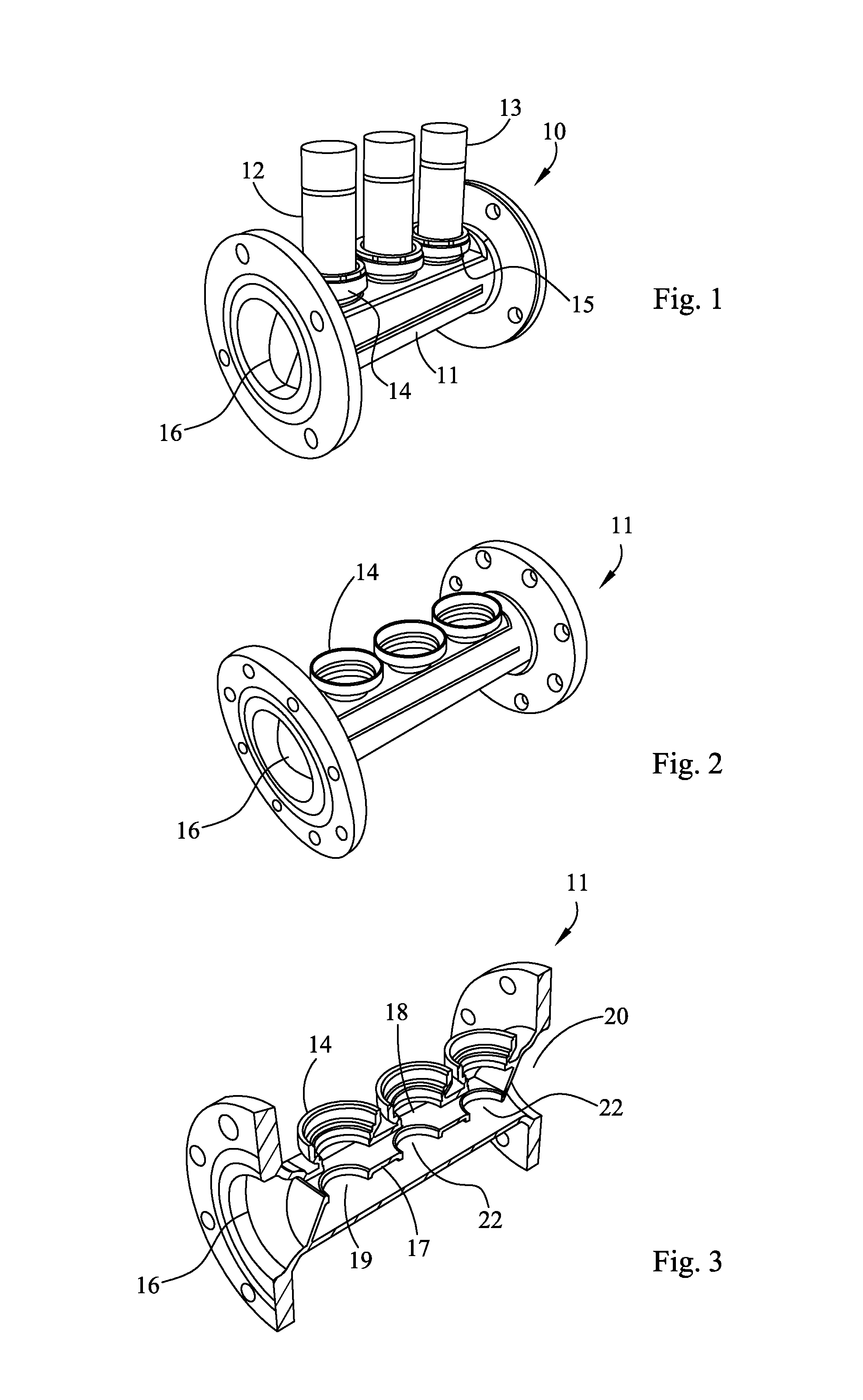
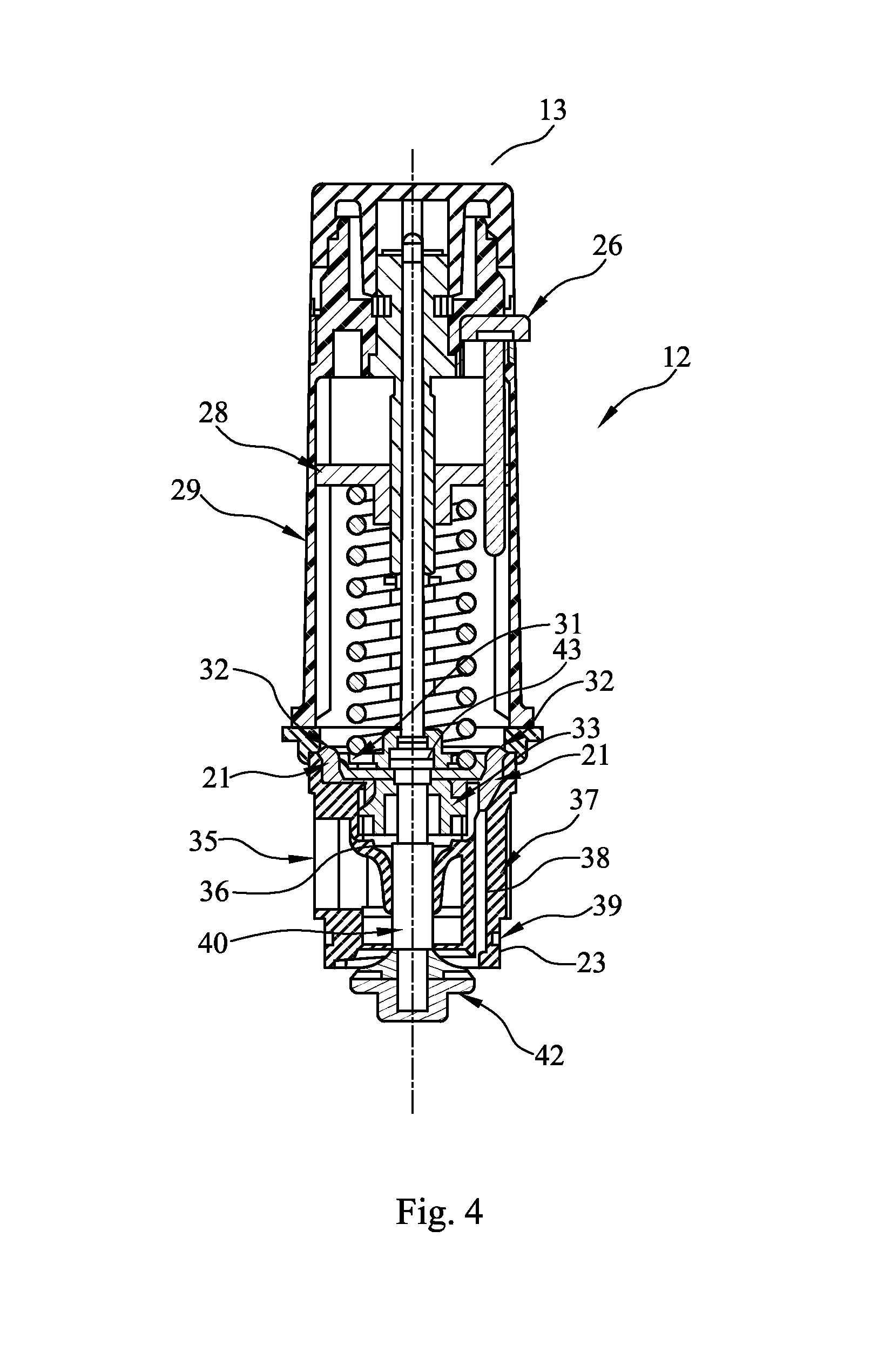
[0024]FIG. 1 shows an illustration of the multi-cartridge pressure regulator 10 of the present invention. The pressure regulator 10 has a conduit 11 and has three valves or valve cartridges 12 on top of conduit 11 wherein the valve cartridges 12 are aligned, preferably, sequentially and in series along the axis of fluid flow. This alignment of the valve cartridges 12 allows for greatest flow of water through the pressure regulator 10. Each valve cartridge 12 has a pressure adjustment knob 13. Conduit 11 has three openings with threaded bases 14 for reversible attachment of the valve cartridges 12. These openings are also a...


PUM


Abstract

A pressure regulator having a conduit with a plurality of adjustable valves inserted reversibly into the conduit. The valves are aligned along the axis of water flow. The interior of the conduit is divided into an inlet chamber and outlet chamber by a septum. The valves are inserted into the inlet chamber, and valve seats protrude through holes in the septum into the outlet chamber, thereby sealing the inlet chamber from the outlet chamber. Fluid flows into the conduit, into the inlet chamber, through the open valve, into the outlet chamber, and then flows out of the conduit. The valves regulate fluid pressure in the outlet chamber. The degree of pressure regulation can be adjusted for each valve by turning pressure adjustment knobs on the top of the valves to produce precise regulation of pressure and fluid flow. A conduit plug can replace a valve in the conduit.

Description

CROSS-REFERENCE TO RELATED APPLICATION[0001]The present application claims priority to U.S. Provisional Patent Application No. 61 / 186,522, filed Jun. 12, 2009, the disclosure of which is incorporated herein by reference.FIELD OF THE INVENTION[0002]The present invention relates to pressure regulators for fluids and, more particularly, to a pressure regulator that has a plurality of adjustable pressure and flow control valves with diaphragm chambers, the valves being positioned in a conduit having an inlet chamber and an outlet chamber.BACKGROUND OF THE INVENTION[0003]In many fluid delivery systems overpressure protection is needed to prevent damage to pipes, conduits, vessels, and the like that may result from excessive fluid pressures. In some cases is it desirable to have a plurality of pressure regulating valves in parallel or in series in order to convey the required flow capacity with reasonably accurate pressure regulation, but this type of system may be complex, expensive and ...

Claims


Application Information

Patent Timeline
IPC IPC(8): F17D1/00G05D16/00
CPCG05D16/0605G05D16/0655G05D16/0404Y10T137/5283Y10T137/782Y10T137/87917
Inventor FRANKLIN, DOUGLAS M.BRILL, JOHN W.
Owner RELIANCE WORLDWIDE CORP
Learn More