
Hands free, controlled autofill for a dispenser

a dispenser and hand-free technology, applied in the direction of instruments, packaging goods, domestic cooling devices, etc., can solve the problems of mechanical and membrane switches that cannot be automatically cut off, springs, levers, etc., and achieve the effect of reducing the number of hands

Active Publication Date: 2012-12-11
WHIRLPOOL CORP
View PDF29 Cites 20 Cited by
  • Summary
  • Abstract
  • Description
  • Claims
  • Application Information

AI Technical Summary

Benefits of technology

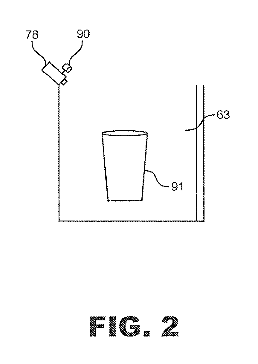
The present invention is a sensing system for a dispenser that uses a digital camera to detect when a container is placed to receive ice or water. The camera is connected to a system that analyzes the images to determine if a container is present and the volume of the container. This information is used to automatically fill the container to a specific level or volume. The camera is mounted in a way that doesn't interfere with changing the bezel on the dispenser. The technical effect of this invention is to improve the efficiency and accuracy of dispensing ice and water.

Problems solved by technology

Over time, mechanical and membrane switches can wear out.
Physical interaction with the switches results in wear and tear on contact points, springs, levers and the like which eventually require replacement.
In addition, most existing systems lack an automatic cut-off feature.
If the user is momentarily distracted, or if the dispenser is operated by an inexperienced individual such as a child, ice and / or water can overflow the container.
However, existing automatic cut-off controls, many of which are based solely on container height, are not overly effective.
If a container is not properly located within the dispenser well, either too little or too much water / ice will be dispensed.
In addition, existing systems are not able to account for various container shapes, such as water bottles, coffee pots and the like.

Method used


Image

  • Hands free, controlled autofill for a dispenser
  • Hands free, controlled autofill for a dispenser
  • Hands free, controlled autofill for a dispenser

Examples


Embodiment Construction

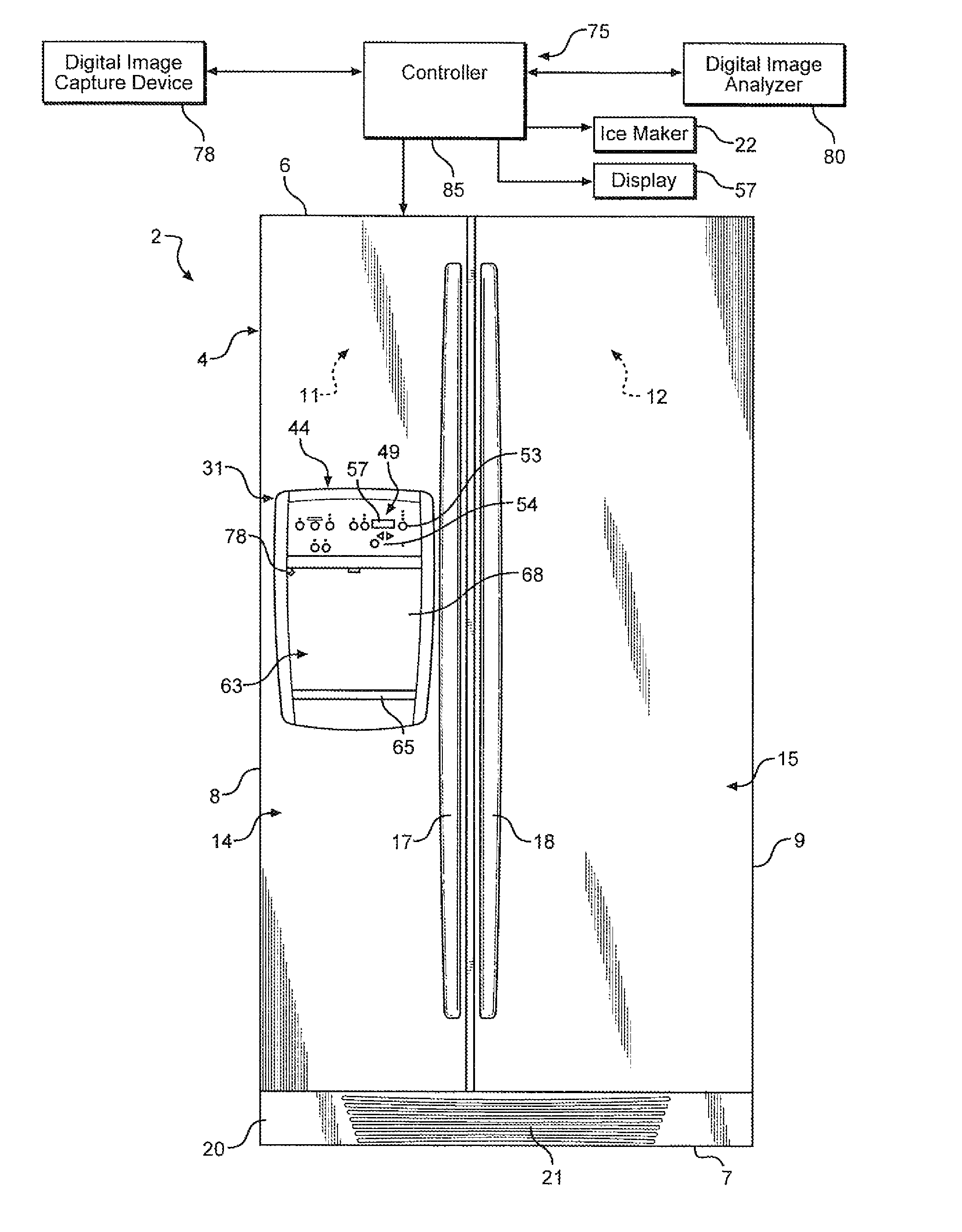
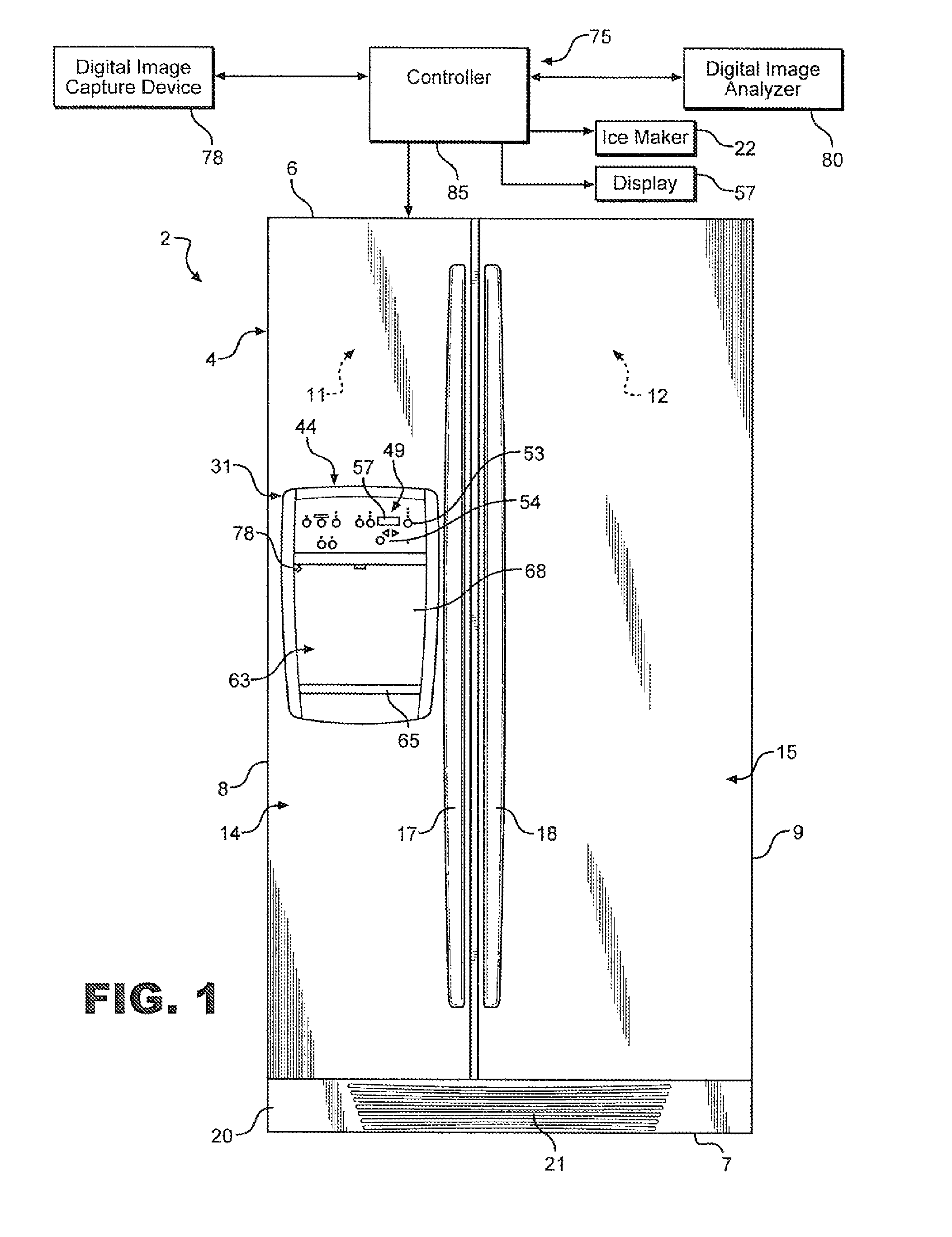
[0014]With initial reference to FIG. 1, a refrigerator constructed in accordance with the present invention is generally indicated at 2. Refrigerator 2 includes a cabinet 4 having a top wall 6, a bottom wall 7 and opposing side walls 8 and 9. In a manner known in the art, refrigerator 2 includes a freezer compartment 11 arranged along side a fresh food compartment 12. Freezer compartment 11 includes a corresponding freezer compartment door 14 and fresh food compartment 12 includes a corresponding fresh food compartment door 15. In a manner also known in the art, each door 14, 15 includes an associated handle 17, 18. Refrigerator 2 is also shown to include a kick plate 20 arranged at a bottom portion thereof having a vent 21 that permits air to flow into refrigeration components (not shown) that establish and maintain desired temperatures in freezer compartment 11 and fresh food compartment 12. In the embodiment shown, refrigerator 2 constitutes a side-by-side model. However, it shou...


PUM

PropertyMeasurementUnit
physical parametersaaaaaaaaaa
volumeaaaaaaaaaa
heightaaaaaaaaaa

Abstract

A dispensing system includes a digital image capture device focused on a dispenser well for capturing images of containers in the dispenser well and a digital image analyzer operatively coupled to the digital image capture device. The digital image analyzer evaluates digital images of containers captured by the digital image capture device to determine physical parameters of each container placed in the dispensing well. An actual dispensing operation is automatically regulated based on characteristics of the container.

Description

[0001]The present invention represents a continuation-in-part of U.S. patent application Ser. No. 12 / 103,170, filed Apr. 15, 2008, pending.BACKGROUND OF THE INVENTION[0002]1. Field of the Invention[0003]The present invention pertains to the art of dispensing and, more particularly, to a sensor system that employs digital imaging technology to determine, among other things, the dimensions and volume of a container positioned in a dispensing well.[0004]2. Description of the Related Art[0005]Refrigerators having built-in ice / water dispensers are well known in the art. In general, the dispensers are mounted to a door of the refrigerator for the purpose of dispensing ice and / or water without requiring a user to access a refrigerator compartment. A typical dispenser includes a dispenser well into which a container is placed. Once the container is in position, an actuator is operated to release the ice and / or water into the container.[0006]In many cases, the actuator is a pressure sensitiv...

Claims


Application Information

Patent Timeline
Patent Type & Authority Patents(United States)
IPC IPC(8): B65B1/30B67D7/08
CPCB67D1/0858B67D1/0888B67D1/1236B67D1/124F25D23/126G07F13/06F25D2700/06
Inventor ASHRAFZADEH, FARHADCHASE, KEVIN M.JANKE, BRIAN P.KANCHANAVALLY, SHREECHARAN
Owner WHIRLPOOL CORP
Learn More