Damping apparatus, use of a shape memory alloy and method for changing damping characteristics

a damping apparatus and shape memory technology, applied in the field of damping apparatus, can solve the problems of inability to offer significant passive damping with energy dissipation in prior art solutions, and achieve the effect of reducing the fatigue life of the damping apparatus

Inactive Publication Date: 2012-12-11
ACANDIS
View PDF18 Cites 36 Cited by
  • Summary
  • Abstract
  • Description
  • Claims
  • Application Information

AI Technical Summary

Benefits of technology

[0009]Furthermore, a NiTi based shape memory alloy phase a stress-strain behavior different from other metallic implant materials: on loading the material exhibits a high stiffness for small strain levels due to the elastic deformation of the austenitic phase, followed by a reduced stiffness for intermediate strain levels (loading / unloading plateau) and finally a large stiffness at large strain levels (elastic deformation of the martensitic phase). This provides an ideal centering force for a dynamic stabilization device with an increased resistance in the central zone of the stabilizer (elastic deformation of the Austenite), much less resistance beyond the central zone of the stabilizer (loading stress plateau) and a high resistance at the end of the range of motion (elastic deformation of the Martensite).
[0035]In a further embodiment, the damping element comprises a first damping element that is configured and adapted to function as a compression spring and a second damping element that is configured and adapted to function as a tension spring. Such an embodiment avoids a reverse cyclic loading of the device, which would undesirably decrease the fatigue life of the damping apparatus.

Problems solved by technology

Moreover, prior art solutions do not offer any significant passive damping with energy dissipation, which is desired to prevent damage to the adjacent portions of the spine.

Method used


Image

  • Damping apparatus, use of a shape memory alloy and method for changing damping characteristics
  • Damping apparatus, use of a shape memory alloy and method for changing damping characteristics
  • Damping apparatus, use of a shape memory alloy and method for changing damping characteristics

Examples


Embodiment Construction

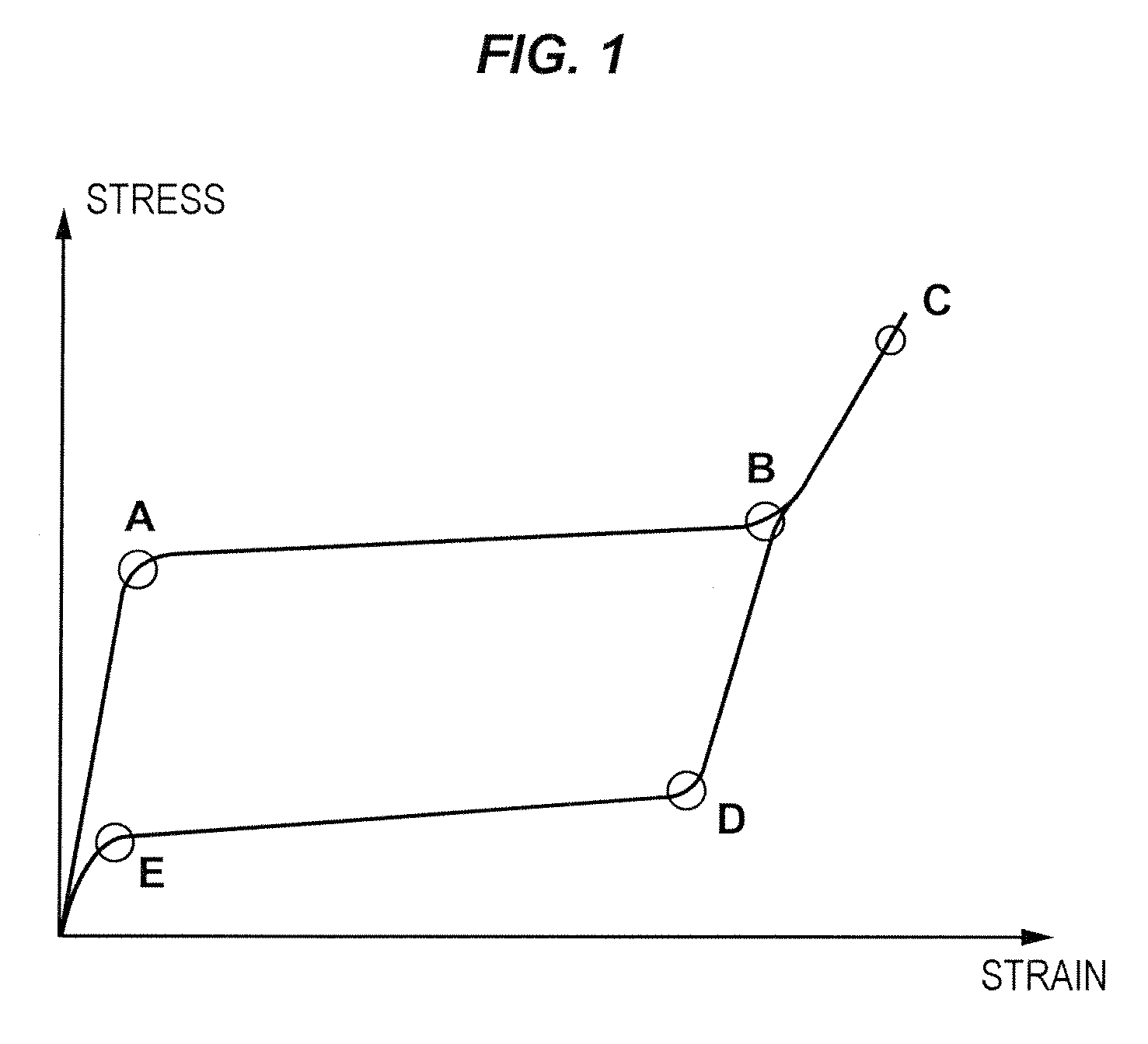
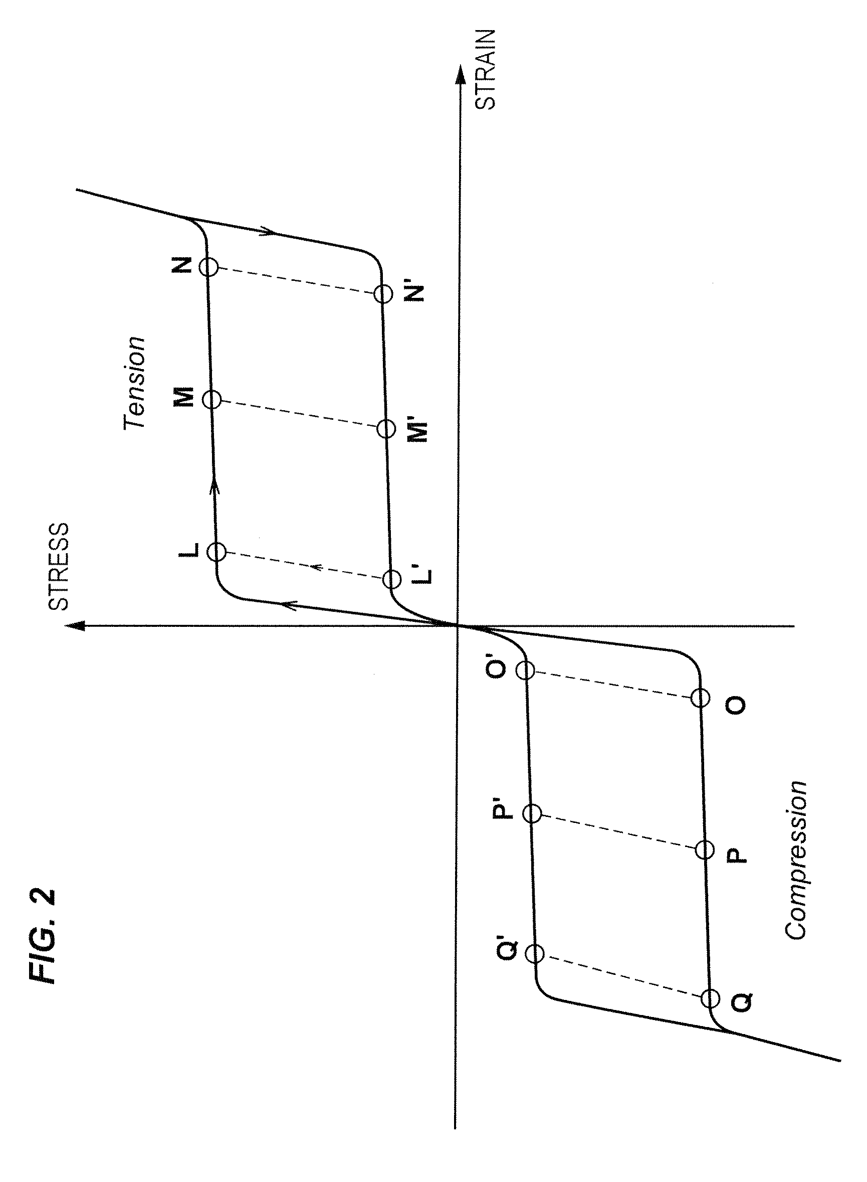
[0042]FIG. 3 shows a damping element consisting out of a SMA tension and a compression spring. The upper spring is the compression spring, the lower spring is the tension spring. Both springs are pre-strained in order to assure that tension and compression occur only in the region of the plateaus. FIG. 3a shows the damping element prior to any loading. In this condition the force of the compression spring correlates to the point 0 or 0′ on the stress strain curve in FIG. 2 depending on the loading or unloading condition. The tension element rests at point L (loading) or L′ (unloading).

[0043]Upon the first tension of the damping element (FIG. 3b) the stress-strain behavior of the tension spring follows the curve L′-L-M (FIG. 2). The translation from L′ to L basically occurs with very little strain but a significant increase in stress (force). After reaching the stress of the superelastic loading plateau the spring strains to point M without any further significant increase of the str...


PUM

PropertyMeasurementUnit
superelastic stress-strain behavioraaaaaaaaaa
temperaturesaaaaaaaaaa
dissipating energyaaaaaaaaaa

Abstract

A damping and shock absorbing method and apparatus for permanent or non-permanent use in the human body and having a shape memory alloy material cycled through stress-strain hysteresis to dissipate energy for effective damping. A sufficiently high pre-stress is applied to the damping element(s) to ensure that the damping working range is within the superelastic cycle. The damping apparatus can work in tension or compression or both in tension and compression. Moreover, damping elements from a shape memory alloy can also work in flexion and extension as well in rotation. The damping apparatus can have a stroke and force suitable for use in the human body by the design, the structure and the chemical composition of the shape memory alloy and their pre-set properties, such as plateau stresses of the superelastic cycle depend on the ambient temperature, the force of damping elements can also be changed in-situ by changing the temperature of the damping elements. The damping elements made out of a shape memory alloy can be combined with elastic elements made out of other materials to achieve stress-strain behavior more suitable for use in the individual human body.

Description

CROSS-REFERENCE TO RELATED APPLICATION[0001]The present application claims the benefit of priority of International Patent Application No. PCT / EP2006 / 009552, filed on Oct. 2, 2006, which application claims priority of European Patent Application No. 05 021 542.5, filed Sep. 30, 2005. The entire text of the priority application is incorporated herein by reference in its entirety.FIELD OF THE DISCLOSURE[0002]The disclosure relates to a method and apparatus to passively damp shocks in the human body, and more particularly, to a spinal stabilization device which absorbs shocks to the elements of the spinal column by dissipating energy.BACKGROUND[0003]Back pain is one of the most widespread deceases in modern societies. After all conservative treatment (non-invasive) options such as medication, physical therapy, chiropractic or osteopathic manipulations and braces are exhausted, patients usually undergo surgical interventions such as laminectomy, discsectomy and finally fusion.[0004]A sp...

Claims


Application Information

Patent Timeline
Patent Type & Authority Patents(United States)
IPC IPC(8): A61F2/44
CPCA61B17/7025A61B17/7031A61F2/442F16F1/021F16F7/00F16F9/16A61B17/7004A61B17/7028A61B2017/00867A61F2002/30014A61F2002/30039A61F2002/30092A61F2002/30563A61F2002/30568A61F2210/0014A61F2250/0018A61F2250/0042F16F2224/0258
Inventor SCHUSSLER, KIRSI
Owner ACANDIS
Why Eureka
Try Eureka