Triaxial acceleration sensor

a technology of acceleration sensor and triaxial acceleration, which is applied in the direction of speed/acceleration/shock measurement, measurement devices, instruments, etc., can solve the problems of large space requirements and comparatively large acceleration sensors

Active Publication Date: 2012-12-18
ROBERT BOSCH GMBH
View PDF14 Cites 23 Cited by
  • Summary
  • Abstract
  • Description
  • Claims
  • Application Information

AI Technical Summary

Benefits of technology

[0005]According to the present invention, an acceleration sensor includes a substrate and a first mass element, which is connected to the substrate in such a way that the first mass element is rotatable about an axis, the first mass element being connected to a second mass element in such a way that the second mass element is movable along a first direction parallel to the axis, and the first mass element being connected to a third mass element in such a way that the third mass element is movable along a second direction perpendicular to the axis. This acceleration sensor may be advantageously designed to be extremely compact.
[0006]The first mass element is preferably designed asymmetrically with respect to the axis. An acceleration acting perpendicularly to the substrate's plane thus causes the mass element to tilt about the axis, which improves its detectability.
[0009]A detection electrode is preferably provided on each side of the axis, both detection electrodes being designed to be symmetrical to each other with respect to the axis. This symmetry provides advantages regarding the linearity and offset stability of the acceleration sensor.
[0010]In one embodiment of the acceleration sensor, the first mass element has a frame, the second mass element being connected to the frame via at least one bending spring which is extensible in the first direction. In another embodiment, the third mass element is connected to the frame via at least one bending spring which is extensible in the second direction. These embodiments make a very compact design of the acceleration sensor possible.

Problems solved by technology

This results in large space requirements and comparatively large acceleration sensors.

Method used


Image

  • Triaxial acceleration sensor
  • Triaxial acceleration sensor
  • Triaxial acceleration sensor

Examples


Embodiment Construction

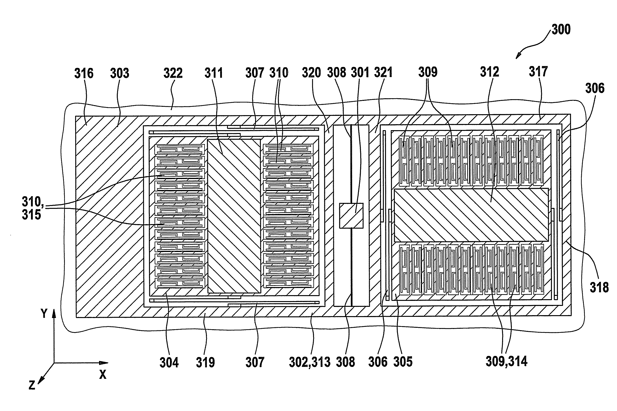
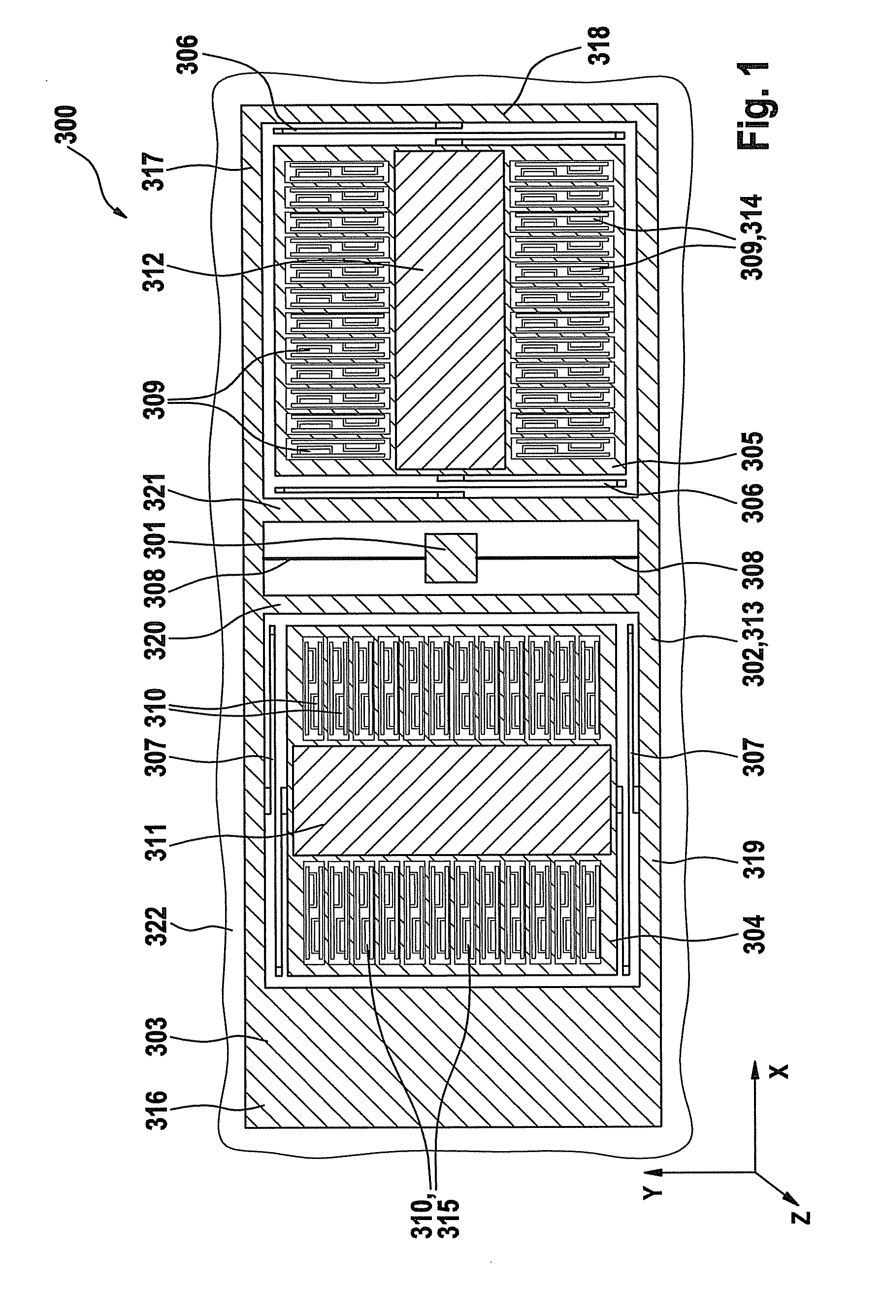
[0015]FIG. 1 shows a schematic representation of a first specific embodiment of an acceleration sensor 300, which is situated in the z direction above a surface of a substrate 322, lying in the x-y plane. Acceleration sensor 300 is suitable for detecting accelerations in all three spatial directions x, y, z. Acceleration sensor 300 is manufactured, for example, from a silicon substrate, as a micromechanical component.

[0016]Acceleration sensor 300 includes an external frame 313, which is situated in the x-y plane. External frame 313 has a rectangular basic shape. The outer edges of external frame 313 are formed by a first frame part 316, a second frame part 317, a third frame part 318, and a fourth frame part 319. First frame part 316 and third frame part 318 are oriented parallel to the y axis. Second frame part 317 and fourth frame part 319 are oriented parallel to the x axis. The area enclosed by first, second, third, and fourth frame parts 316, 317, 318, 319 is subdivided into th...


PUM


Abstract

An acceleration sensor includes a substrate and a first mass element, which is connected to the substrate in such a way that the first mass element is rotatable about an axis, the first mass element being connected to a second mass element in such a way that the second mass element is movable along a first direction parallel to the axis, and the first mass element being connected to a third mass element in such a way that the third mass element is movable along a second direction perpendicular to the axis.

Description

FIELD OF THE INVENTION[0001]The present invention relates to an acceleration sensor having a mass situated over a plane of a substrate.BACKGROUND INFORMATION[0002]Triaxial acceleration sensors, in particular triaxial micromechanical acceleration sensors, are needed for applications in entertainment and automotive electronics. A maximally compact design of the acceleration sensors is desired in those cases.[0003]The basic principle of micromechanical acceleration sensors is that a seismic mass is movably supported with respect to stationary electrodes on a substrate with the aid of a suspension. The seismic mass and the stationary electrodes form one or more capacitors. A deflection of the seismic mass caused by an acceleration acting on the micromechanical acceleration sensor results in a change in the capacitances of these capacitors, which may be detected and represents a measure of the magnitude of the effective acceleration. To avoid zero deviations, capacitance changes are pref...

Claims


Application Information

Patent Timeline
Patent Type & Authority Patents(United States)
IPC IPC(8): G01P15/125G01P15/18
CPCG01P15/125G01P15/18G01P2015/0814G01P2015/0831
Inventor CLASSEN, JOHANNESTEBJE, LARS
Owner ROBERT BOSCH GMBH
Why Eureka
Try Eureka