Stacked barcode reader and stacked barcode reading method

a barcode reader and stacked technology, applied in the field of stacking barcode readers, can solve the problems of deviating the scanned reflection coefficient waveform of the stacking barcode, affecting affecting the accuracy of the stacked barcode reading, so as to improve the reading performance of the barcode reader, improve the accuracy of reading, and reduce the number of decoded code words

Inactive Publication Date: 2012-12-18
SANKYO SEIKI MFG CO LTD
View PDF11 Cites 6 Cited by
  • Summary
  • Abstract
  • Description
  • Claims
  • Application Information

AI Technical Summary

Benefits of technology

[0007]An objective of the present invention, then considering such a problem, is to provide a stacked barcode reader that is minimally affected by the deviation of the scanned reflection coefficient waveform of the stacked barcode to accurately read the stacked barcode, and a stacked barcode reading method.
[0020]According to a stacked barcode reader and a stacked barcode reading method of the present invention, a stacked barcode can be accurately read while minimally affected by the deviation of a scanned reflection coefficient waveform of the stacked barcode.
[0021]According to the stacked barcode reader and stacked barcode reading method of the present invention, the priority order of T-sequence is determined based on the evaluation values (the maximum value, variance or the like) of the frequency distribution of the line widths of the bars and the spaces which configure the stacked barcode; therefore, despite the resolution of the image pickup optical system, the number of errors in all the decoded code words is reduced to improve the reading performance of the barcode reader on the stacked barcode. Consequently, while being minimally affected by the deviation of the scanned reflection coefficient waveform of the stacked barcode, the stacked barcode can be read more accurately.

Problems solved by technology

However, if the resolution of the image pickup optical system that scans stacked barcodes is not at a predetermined level, a scanned reflection coefficient waveform of the stacked barcode deviates.
For this reason, it is a problem that a boundary between a bar and a space cannot be accurately detected due to the deviated scanned reflection coefficient waveform.
Consequently, accuracy of reading the stacked barcode may be degraded.

Method used


Image

  • Stacked barcode reader and stacked barcode reading method
  • Stacked barcode reader and stacked barcode reading method
  • Stacked barcode reader and stacked barcode reading method

Examples


embodiment 1

of the Invention

[0043]FIG. 1 through FIG. 16 show an embodiment 1 of the present invention. In Embodiment 1, an image pickup device 11 is used for an imaging section; a data processing device 13 is used for an data processing section; a threshold calculating means 14a is used for a line width calculating means; a fixed threshold calculating means 14a1 and a local threshold calculating means 14a2 are used for a binary threshold calculating means; a T-sequence measuring section 15 is used for a T-sequence measuring means; a code word converting section 16 is used for a code word obtaining means; and a priority order deciding section 17 is used for a priority order deciding means.

[0044]Stacked Barcode Reader

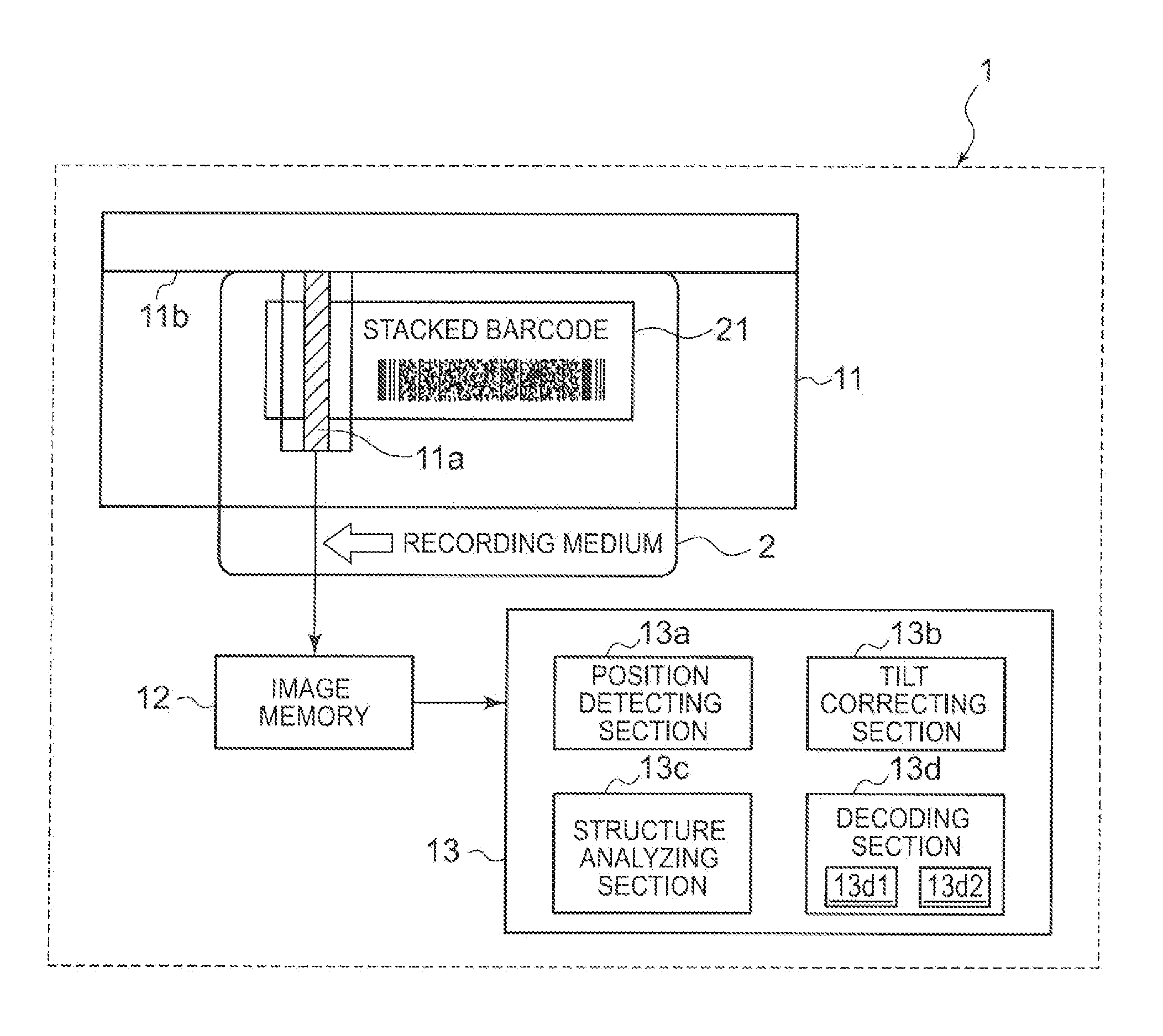
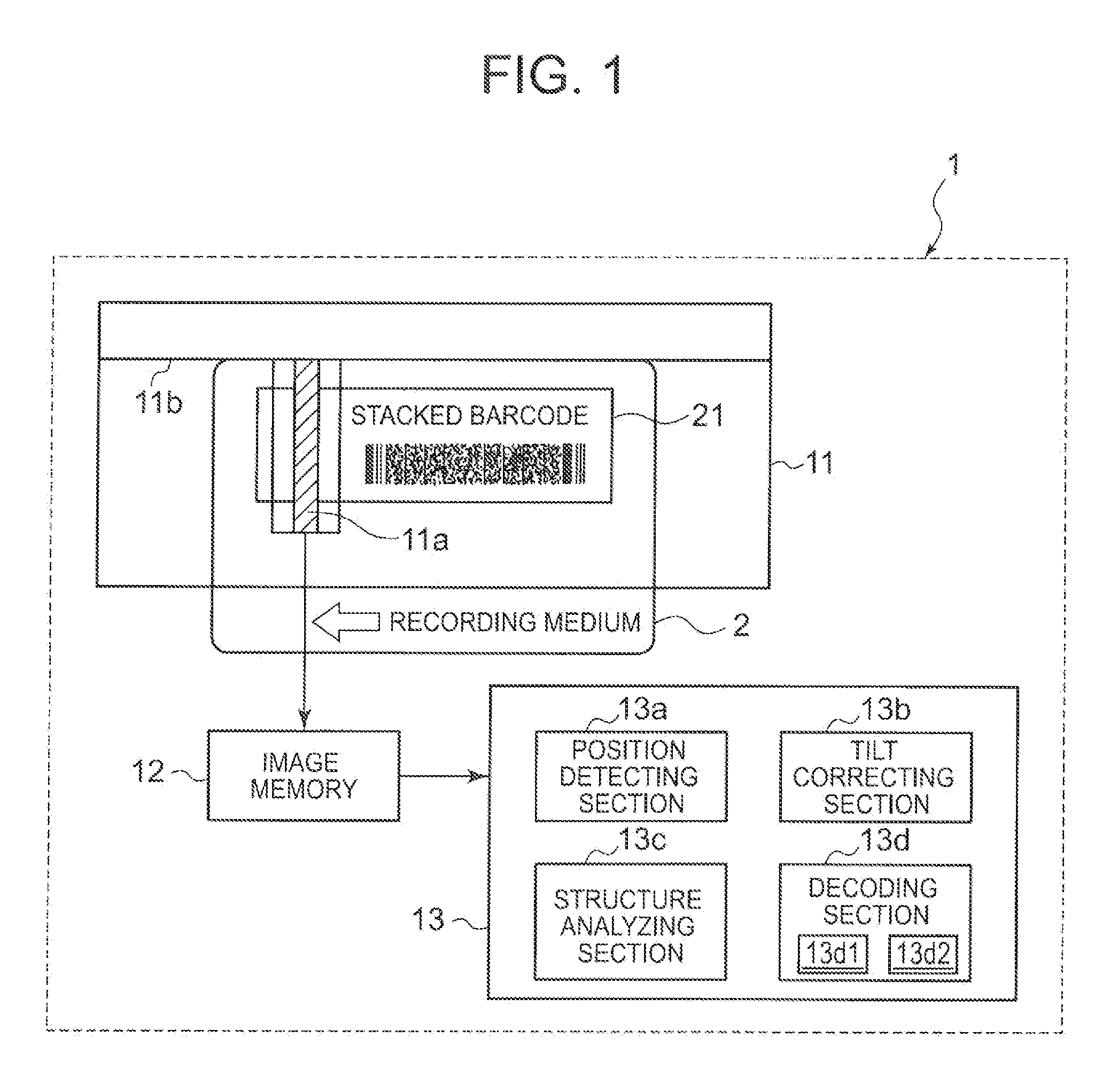
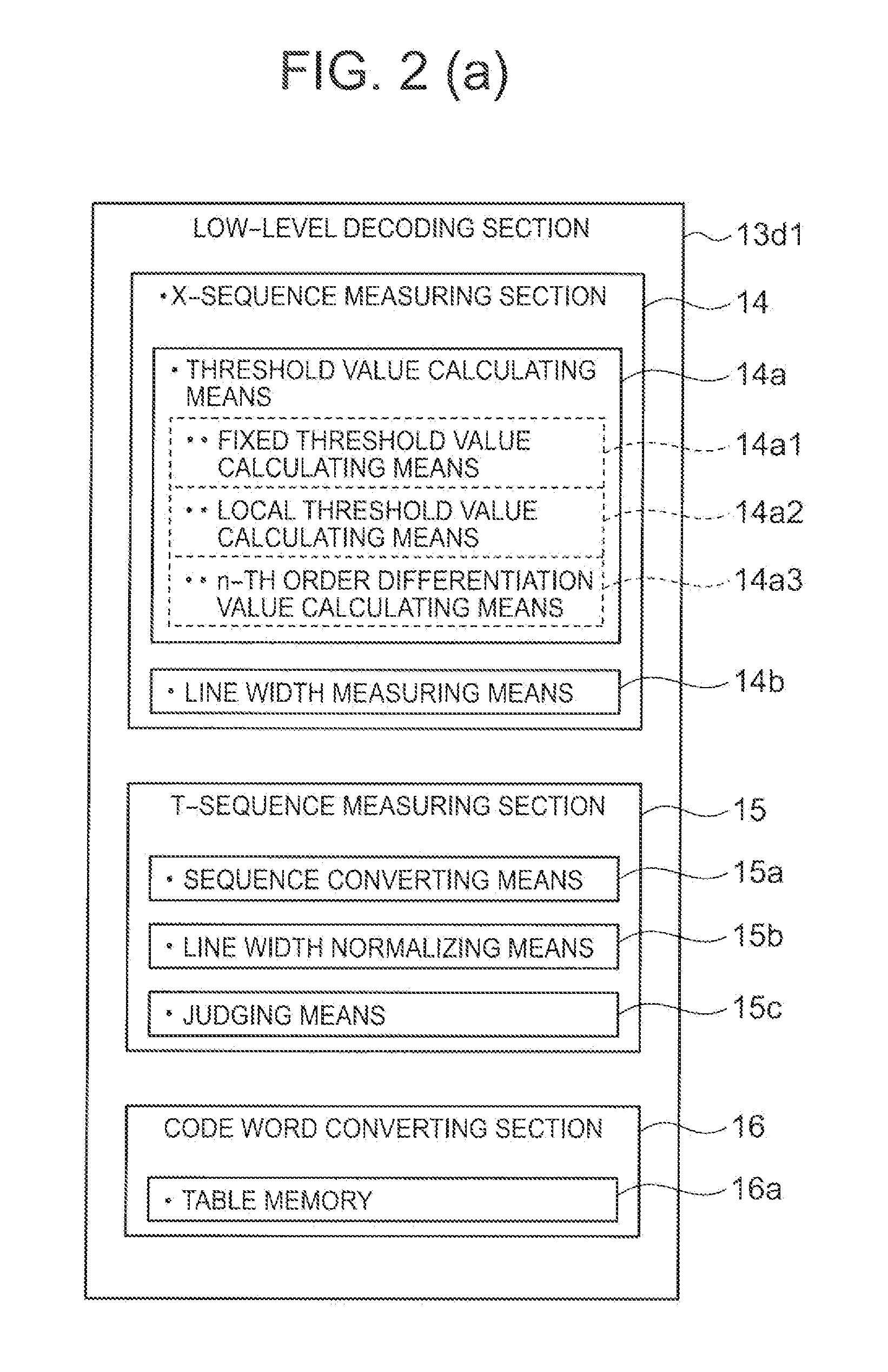
[0045]FIG. 1 is a block diagram of an electrical configuration of a stacked barcode reader 1 of an embodiment 1 of the present invention. FIG. 2 (a) is a block diagram of a low-level decoding section of the stacked barcode reader of Embodiment 1.

[0046]In FIG. 1, the stacked barcode ...

embodiment 2

of the Invention

[0161]Embodiment 2 of the present invention is described hereinafter.

[0162]Embodiment 2 of the present invention is shown in FIG. 1 through FIG. 17. Note that since a block diagram of an electrical configuration of a stacked barcode reader, a diagram showing an example of the stacked barcode, a flow chart of a stacked barcode reading method and the like in Embodiment 2 of the present invention are similar to those of the above-described embodiment 1 of the present invention, the same figures are used for FIG. 1, FIG. 3 through FIG. 10 and FIG. 12 to FIG. 16. To simplify the description, the descriptions for these portions are omitted, and the same numbers as those in Embodiment 1 are used in the descriptions for the configuration having the same function. Hereinafter, Embodiment 2 is described using FIG. 2 (b), FIG. 11(b) and FIG. 17 focusing on the different points from the above-described embodiment 1.

[0163]FIG. 1 through FIG. 17 show an embodiment 2 of the present...


PUM


Abstract

In a decoding section of a stacked barcode reader, the brightness values of multiple pixels configuring image data are used to calculate multiple line widths of the bars and the spaces of the stacked barcode. Based on the evaluation value of the frequency distribution of multiple line widths, a priority order of T-sequence is determined. According to this priority order, the T-sequence is measured and the code word corresponding to the T-sequence is obtained. With this, the priority order of the T-sequence is determined based on the evaluation value (such as the maximum value, variance, etc.) of the frequency distribution of the line widths of the bars and the spaces that configure the stacked barcode increasing reading performance of the barcode reader on a stacked barcode while reducing the number of errors in all the decoded code words, despite the level of the resolution of the image pickup optical system.

Description

[0001]The present application claims priority from Japanese Patent Application Nos. JP 2010-227437 filed on Oct. 7, 2010, and JP 2010-227438 filed on Oct. 7, 2010, the disclosures of which are incorporated herein by reference in their entirety.FIELD OF THE INVENTION[0002]The present invention relates to a stacked barcode reader that optically reads stacked barcodes and relates to a stacked barcode reading method.DESCRIPTION OF RELATED ART[0003]As a conventional means to give specific data to a paper or plastic medium and be automatically recognized, a barcode in which character data is coded into a barcode and displayed by bars and spaces has been widely used. For example, a 1-dimensional barcode is used for customer goods. In recent years, a 2-dimensional barcode which has greater capacity (data density) than the 1D barcode has been introduced responding to a demand to increase the data amount in barcodes. A reading device responding to this 2D barcode has gradually become widespre...

Claims


Application Information

Patent Timeline
Patent Type & Authority Patents(United States)
IPC IPC(8): G06K7/10
CPCG06K7/10712G06K7/10851
Inventor NAKAMURA, HIROSHI
Owner SANKYO SEIKI MFG CO LTD
Why Eureka
Try Eureka