Knee bolster for vehicles

a technology for knee bolsters and vehicles, which is applied in the direction of vehicular safety arrangements, vehicle components, pedestrian/occupant safety arrangements, etc., can solve the problems of airbags not being able to successfully protect passengers from crash energy, the knee bolster cannot efficiently absorb the load applied to the knees of passengers, and the head and chest of passengers

Active Publication Date: 2012-12-18
HYUNDAI MOTOR CO LTD +1
View PDF6 Cites 9 Cited by
  • Summary
  • Abstract
  • Description
  • Claims
  • Application Information

AI Technical Summary

Benefits of technology

[0011]Various aspects of the present invention are directed to provide a knee bolster for vehicles, in which a combined structure of a U-shaped bracket and a shock absorbing foam is adapted and thus the knee load of a passenger involved in an accident can be absorbed by two deformations, of the U-shaped bracket and deformation of the shock absorbing foam, so that the knee bolster can achieve compliance with the pedestrian protection regulations of the reinforced North American NCAP.
[0012]In an aspect of the present invention, a knee bolster for vehicles, which may be placed inside a lower instrument panel of a vehicle and may be mounted to a cowl cross bar and relieves shock applied to knees of a passenger in case of an accident, may include a U-shaped bracket mounted to the cowl cross bar and bent to form a U-shape to be deformed by an external force during the accident, thus primarily absorbing knee load of the passenger, and a shock absorbing foam mounted in the U-shaped bracket, being deformed by the external force during the accident, and sliding along inner surface of the U-shaped bracket, thus secondarily absorbing the knee load of the passenger.
[0021]As described above, the knee bolster for vehicles according to the present invention uses a combined structure of a U-shaped bracket and shock absorbing foam and thus can absorb the knee load of a passenger in an accident by two deformations, namely, of the U-shaped bracket and deformation of the shock absorbing foam, so that the knee bolster can achieve compliance with the pedestrian protection regulations of the reinforced North American NCAP.

Problems solved by technology

In the above state, when the lower instrument panel is easily deformed, the knees of the front passengers may exceedingly move forwards so that the heads and chests of the passengers may lean backwards too much and airbags may fail to successfully protect the passengers from the crash energy.
However, the conventional knee bolster is designed such that absorption of the knee load in an accident can be realized by the knee bolster bracket 2 deforming, so that the conventional knee bolster cannot efficiently absorb the load applied to the knees of the passenger and does not achieve compliance with the pedestrian protection regulations of the reinforced North American NCAP.
However, the conventional knee bolster technique cannot achieve compliance with the pedestrian protection regulations of the reinforced North American NCAP.

Method used


Image

  • Knee bolster for vehicles
  • Knee bolster for vehicles
  • Knee bolster for vehicles

Examples


Embodiment Construction

[0036]Reference will now be made in detail to various embodiments of the present invention(s), examples of which are illustrated in the accompanying drawings and described below. While the invention(s) will be described in conjunction with exemplary embodiments, it will be understood that present description is not intended to limit the invention(s) to those exemplary embodiments. On the contrary, the invention(s) is / are intended to cover not only the exemplary embodiments, but also various alternatives, modifications, equivalents and other embodiments, which may be included within the spirit and scope of the invention as defined by the appended claims.

[0037]Hereinbelow, a knee bolster for vehicles according to an exemplary embodiment of the present invention will be described with reference to the accompany drawings.

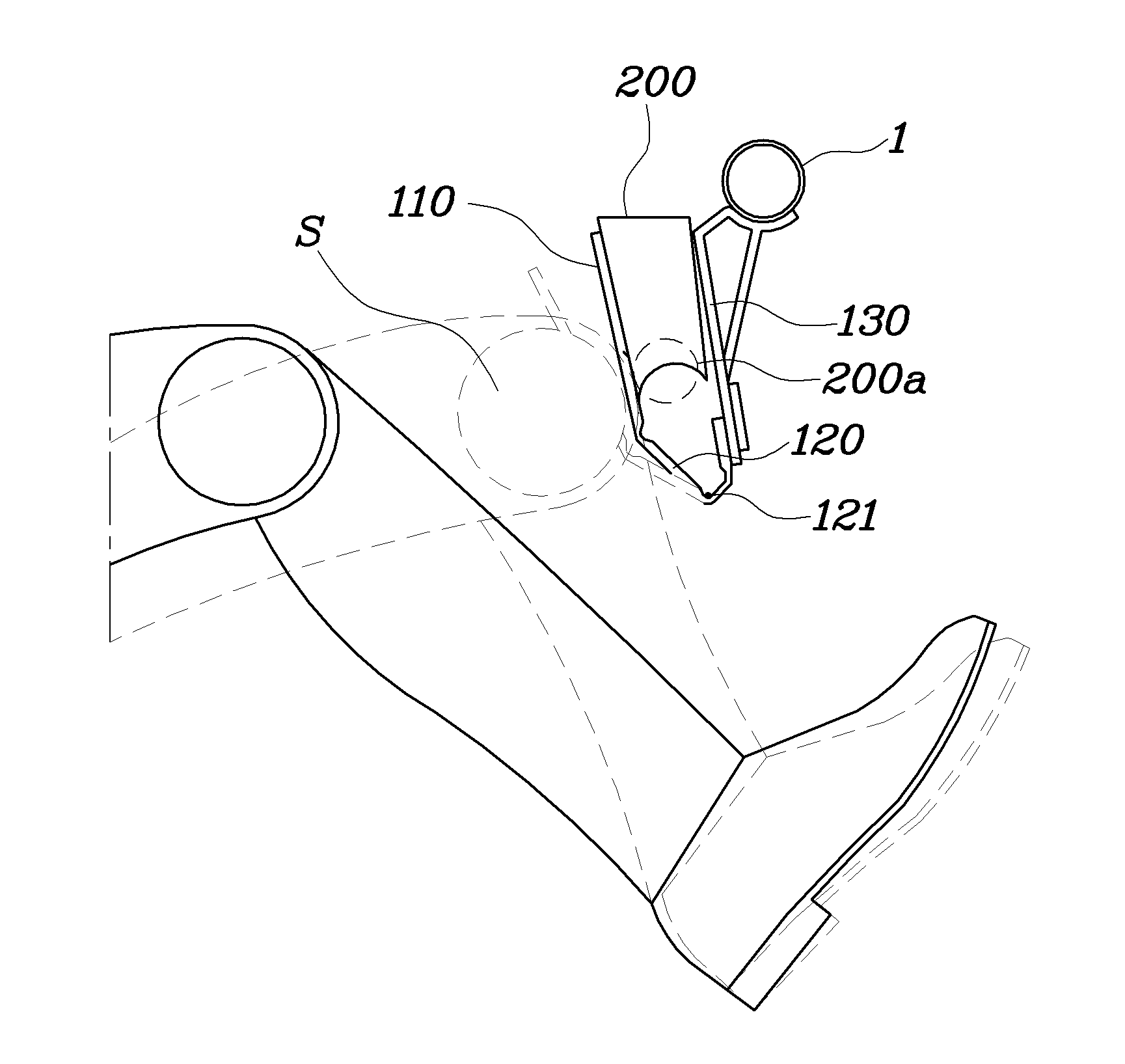
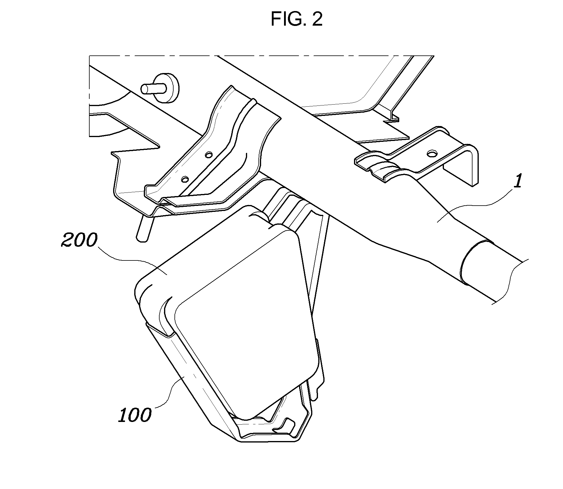
[0038]As shown in FIG. 2 through FIG. 4, the knee bolster for vehicles according to the exemplary embodiment of the present invention is a shock absorbing device, which...


PUM


Abstract

A knee bolster for vehicles, which is placed inside a lower instrument panel of a vehicle and is mounted to a cowl cross bar and relieves shock applied to knees of a passenger in case of an accident, may include a U-shaped bracket mounted to the cowl cross bar and bent to form a U-shape to be deformed by an external force during the accident, thus primarily absorbing knee load of the passenger, and a shock absorbing foam mounted in the U-shaped bracket, being deformed by the external force during the accident, and sliding along inner surface of the U-shaped bracket, thus secondarily absorbing the knee load of the passenger.

Description

CROSS-REFERENCE TO RELATED APPLICATIONS[0001]The present application claims priority to Korean Patent Application No. 10-2010-0091706 filed on Sep. 17, 2010, the entire contents of which is incorporated herein for all purposes by this reference.BACKGROUND OF THE INVENTION[0002]1. Field of the Invention[0003]The present invention relates, in general, to a knee bolster for vehicles and, more particularly, to a knee bolster for vehicles, which achieves compliance with the pedestrian protection regulations of the reinforced North American NCAP (New Car Assessment Program) in crash tests and can minimize the production cost, and can simplify the production process.[0004]2. Description of Related Art[0005]Generally, in car accidents, passengers including the driver sitting in the front seat of a vehicle move forwards and come into contact with the lower instrument panel placed in front of the front seats. In the above state, when the lower instrument panel is easily deformed, the knees of...

Claims


Application Information

Patent Timeline
Patent Type & Authority Patents(United States)
IPC IPC(8): B60R21/045
CPCB60R21/045B60R2021/0051
Inventor AN, JAE HYUN
Owner HYUNDAI MOTOR CO LTD
Why Eureka
Try Eureka