System for controlling at least two variable-geometry equipments of a gas turbine engine, particularly by rack

a technology of variable geometry and control system, which is applied in the direction of wind motors, machines/engines, wind turbines with perpendicular air flow, etc., can solve the problems of increasing the risk of stopping, the weight, the cost and space requirements of these control systems for equipments are relatively high, and the risk of induced risks is considerable. achieve the effect of facilitating the control of two variable geometry equipments by a single actuator

Active Publication Date: 2012-12-25
SN DETUDE & DE CONSTR DE MOTEURS DAVIATION S N E C M A
View PDF10 Cites 3 Cited by
  • Summary
  • Abstract
  • Description
  • Claims
  • Application Information

AI Technical Summary

Benefits of technology

[0010]By using a single actuator for controlling several (at least two) variable-geometry equipments, the control system makes it possible to reduce the number of parts of the gas turbine engine and thereby achieve the objective of the invention, while retaining said equipments on distinct cores, allowing them thereby to fulfill their function. The weight, the volume and the cost of a second control system are, at least largely, avoided, since the equipments of the first and second cores are actuated by the same actuator.
[0014]According to one embodiment, in the case of an engine with a high-pressure core and a low-pressure core, the variable-geometry equipments of the high-pressure core are situated close to the low-pressure core (for example close to the upstream side of the high-pressure core). The mechanical connection between the actuator and the equipments that it controls is therefore made easier.
[0022]According to one embodiment, the actuator of the control system comprises at least one movable actuation member the movements of which make it possible to actuate the variable-geometry equipments.
[0025]According to one embodiment, a means of disengagement is provided between the actuator and at least one of the equipments, said means being arranged to disengage said equipment from the actuator outside the range of actuation of said equipment; therefore, in such a range of the actuation parameter, irrespective of the variations of the parameter, the actuator does not (or not significantly) act on the equipment in question, which is therefore disengaged from the actuator. It is also said that such a range of values of the actuation parameter, in which the actuation member of the actuator is in movement but does not actuate the equipment in question, forms, for said equipment, a “free travel” of the actuation member. The disengagement device makes it possible to reserve a range of values of the actuation parameter solely for controlling the other equipment(s). This is advantageous when the equipment in question must not be affected even when the control of one of the other equipments that are controlled must be able to vary.
[0026]According to a particular embodiment, at least one portion of the range of actuation of the first equipment is outside the range of actuation of the second equipment. Control by a single actuator of two variable-geometry equipments may be made easier by the fact that the ranges of actuation of both equipments do not match totally, making it possible, outside the common zone, to actuate one equipment without actuating the other.
[0029]According to a particular embodiment, the range of actuation of one of the first and second equipments is entirely contained in the range of actuation of the other equipment. In this case, the equipments are actuated simultaneously in their common zone, which may have advantages depending on the nature of the equipment, as seen above; in addition, such an embodiment may make it possible to provide a greater amplitude of actuation for one of the two equipments.

Problems solved by technology

The result of this is that the weight, the cost and the space requirement of these control systems for the equipments are relatively high.
Although the saving thus made is significant (the actuators, the servovalves, the pipework, the harnesses, etc. that are associated thereby are removed), the risks induced are considerable, particularly at idle speed if water or hail enters the engine causing an increased risk of stopping the latter.

Method used


Image

  • System for controlling at least two variable-geometry equipments of a gas turbine engine, particularly by rack
  • System for controlling at least two variable-geometry equipments of a gas turbine engine, particularly by rack
  • System for controlling at least two variable-geometry equipments of a gas turbine engine, particularly by rack

Examples


Embodiment Construction

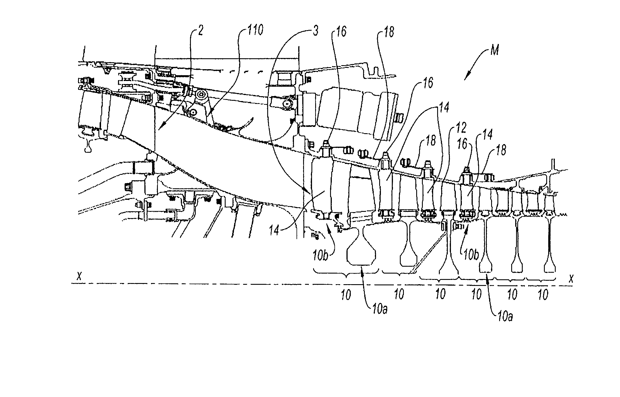
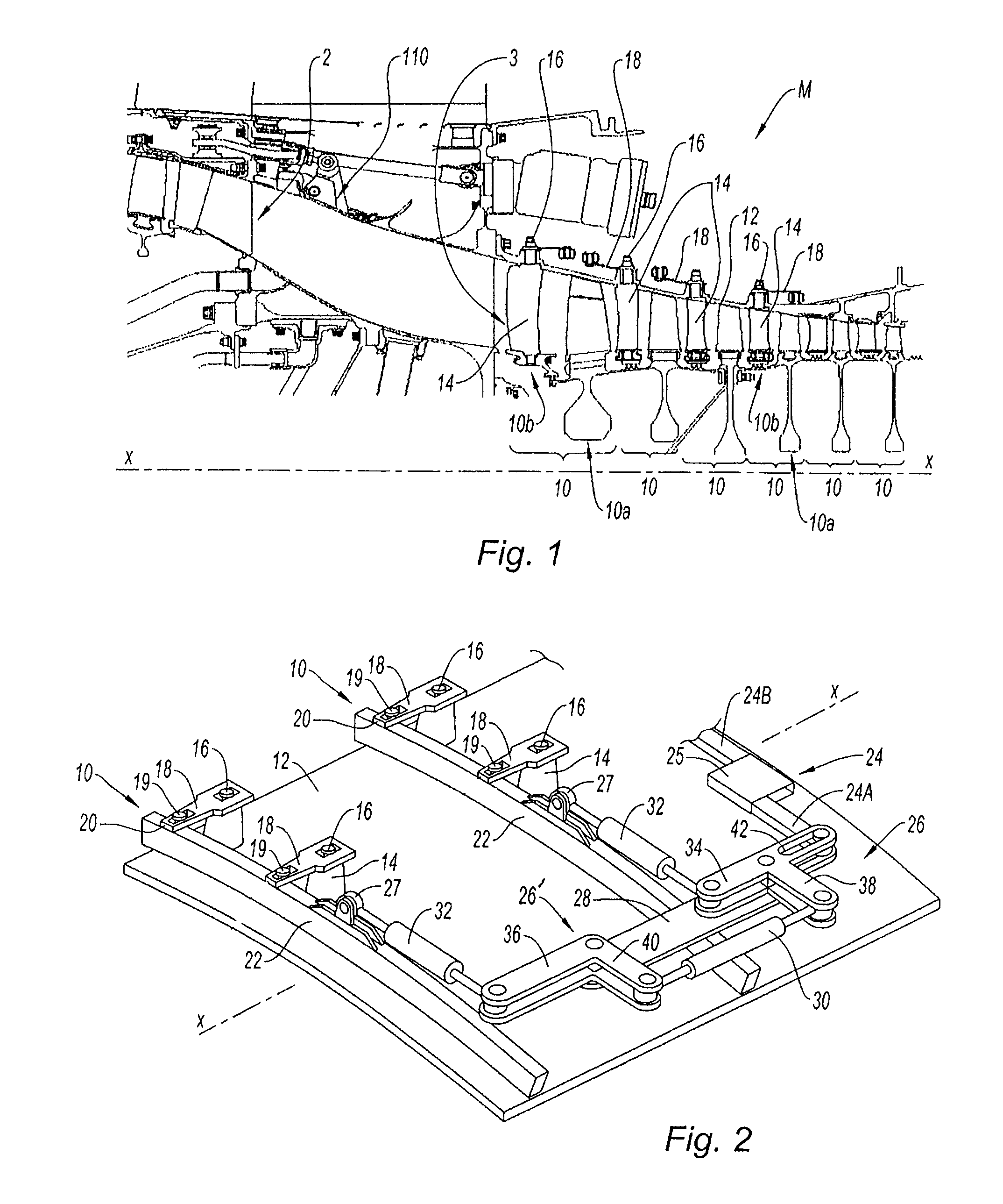
[0045]In a known manner, a gas turbine engine M, in this instance a dual-core turbojet with an axis X-X comprises, from upstream to downstream, a fan, not shown, a low-pressure compressor 2 (frequently called a “booster” by those skilled in the art), a high-pressure compressor 3, a combustion chamber, a high-pressure turbine, a low-pressure turbine and a nozzle for exhausting the gases (not shown). Hereinafter, the following abbreviations will be used: LP for low pressure and HP for high pressure.

[0046]The HP compressor 3 and the HP turbine are attached to a single shaft, called the high-pressure shaft, and therefore belong to the HP core of the engine M, while the LP compressor 2 and the LP turbine are attached to a single shaft, called the low-pressure shaft, and therefore belong to the LP core of the engine.

[0047]The HP compressor 3 comprises at least one stage 10 formed of a disk 10a of movable blades and a disk 10b of fixed blades (also called stator blades). Each disk 10a, 10b...


PUM


Abstract

A system for controlling at least two variable-geometry equipments of a gas turbine engine is disclosed. The engine includes at least a first core rotating at a first speed and a second core rotating at a second speed. The first equipment includes at least one variable-pitch stator blade of a compressor of the first core and the second equipment includes at least one air bleed valve of a compressor of the second engine core moving between an open position at idle speed and a closed position at high speed. The system includes an actuator which actuates both equipments.

Description

BACKGROUND OF THE INVENTION[0001]The present invention relates to the general field of the control of variable-geometry equipments of a gas turbine engine. The invention more particularly relates to the optimization of the control of several equipments forming part of distinct cores of the engine.[0002]“Variable-geometry equipment” means in this instance an equipment that is connected to a control member and of which the dimension, the shape, the position and / or the speed is or are capable of being modified, according to detected events or defined parameters, in order to act on the operation of the engine. Examples of variable-geometry equipments are air bleed valves (with variable aperture) of a low-pressure compressor, fixed blades of a variable-pitch high-pressure compressor, turbine blades of which the clearance at the tip is variable, variable flow-rate fuel pumps, etc.[0003]“Core” conventionally designates a subassembly of a gas turbine engine comprising as main members a comp...

Claims


Application Information

Patent Timeline
Patent Type & Authority Patents(United States)
IPC IPC(8): F04D29/56
CPCF01D17/16F01D17/20F02C9/18F02C9/22F02C6/08F05D2270/58F04D27/0215F04D27/023F04D27/0246F04D29/563
Inventor COLOTTE, BAPTISTE BENOITGAULLY, BRUNO ROBERT
Owner SN DETUDE & DE CONSTR DE MOTEURS DAVIATION S N E C M A
Why Eureka
Try Eureka