Method and System for Wafer Temperature Control

a technology of temperature control system and temperature setpoint, which is applied in the direction of process and machine control, electrical equipment, instruments, etc., can solve the problems of temperature exceeding the cooling capabilities of the temperature control system, the type of technique may be somewhat problematic, and the error between a temperature setpoint and an actual temperature to be reduced more effectively, the cost and complexity of the wafer temperature control system, and hence the process tool itself, to be reduced, and the effect of increasing the response tim

Inactive Publication Date: 2008-04-24
BROOKS INSTRUMENT
View PDF9 Cites 2 Cited by
  • Summary
  • Abstract
  • Description
  • Claims
  • Application Information

AI Technical Summary

Benefits of technology

[0015] Embodiments of the present invention may provide the technical advantage of allowing the temperature of a wafer, or a surrogate thereof, and other process variables, to be taken into account when controlling the temperature of the wafer. By utilizing a chiller and subsystems intended to regulate the pressure of gas to the backside of wafer together certain embodiments of the present invention may also provide the technical advantage of allowing both coarse and fine grained temperature control to be utilized in combination. By allowing both coarse and fine grained temperature control not only may error between a temperature setpoint and an actual temperature be reduced more effectively, but additionally, a ramp for any temperature changes that are needed may more easily be optimized.
[0016] Furthermore, some of the embodi

Problems solved by technology

These types of techniques may be somewhat problematic, however, as the use of chillers may only be adequate to accomplish gross control over the temperature of a wafer in a process chamber.
This technique is problematic as well.
Thus, in some manufacturing processes the temperature of a wafer may exceed the cooling capabilities of a temperature control system utilizing a backside cooling gas.
Furthermore, in some cases the wafer may be so large that in order to maintain a desired wafer temperature multiple zones of a wafer may need to be established and the pressure of gas in each of these zones controlled, greatly increasingly the complexity of these temperature control systems.
Temperature c

Method used


Image

  • Method and System for Wafer Temperature Control
  • Method and System for Wafer Temperature Control
  • Method and System for Wafer Temperature Control

Examples


Embodiment Construction

[0026] The invention and the various features and advantageous details thereof are explained more fully with reference to the nonlimiting embodiments that are illustrated in the accompanying drawings and detailed in the following description. Descriptions of well known starting materials, processing techniques, components and equipment are omitted so as not to unnecessarily obscure the invention in detail. It should be understood, however, that the detailed description and the specific examples, while indicating preferred embodiments of the invention, are given by way of illustration only and not by way of limitation. After reading the specification, various substitutions, modifications, additions and rearrangements which do not depart from the scope of the appended claims will become apparent to those skilled in the art from this disclosure.

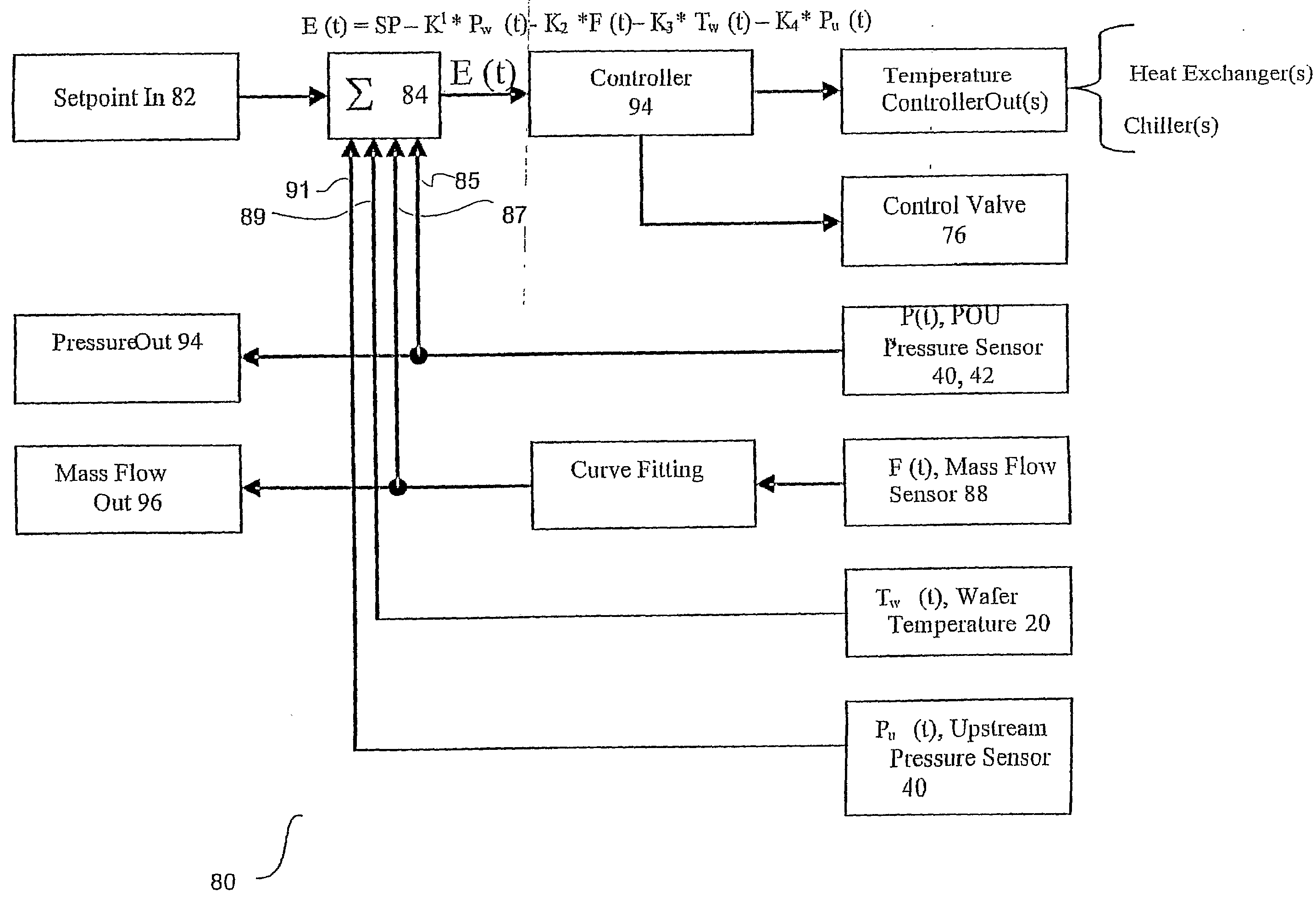
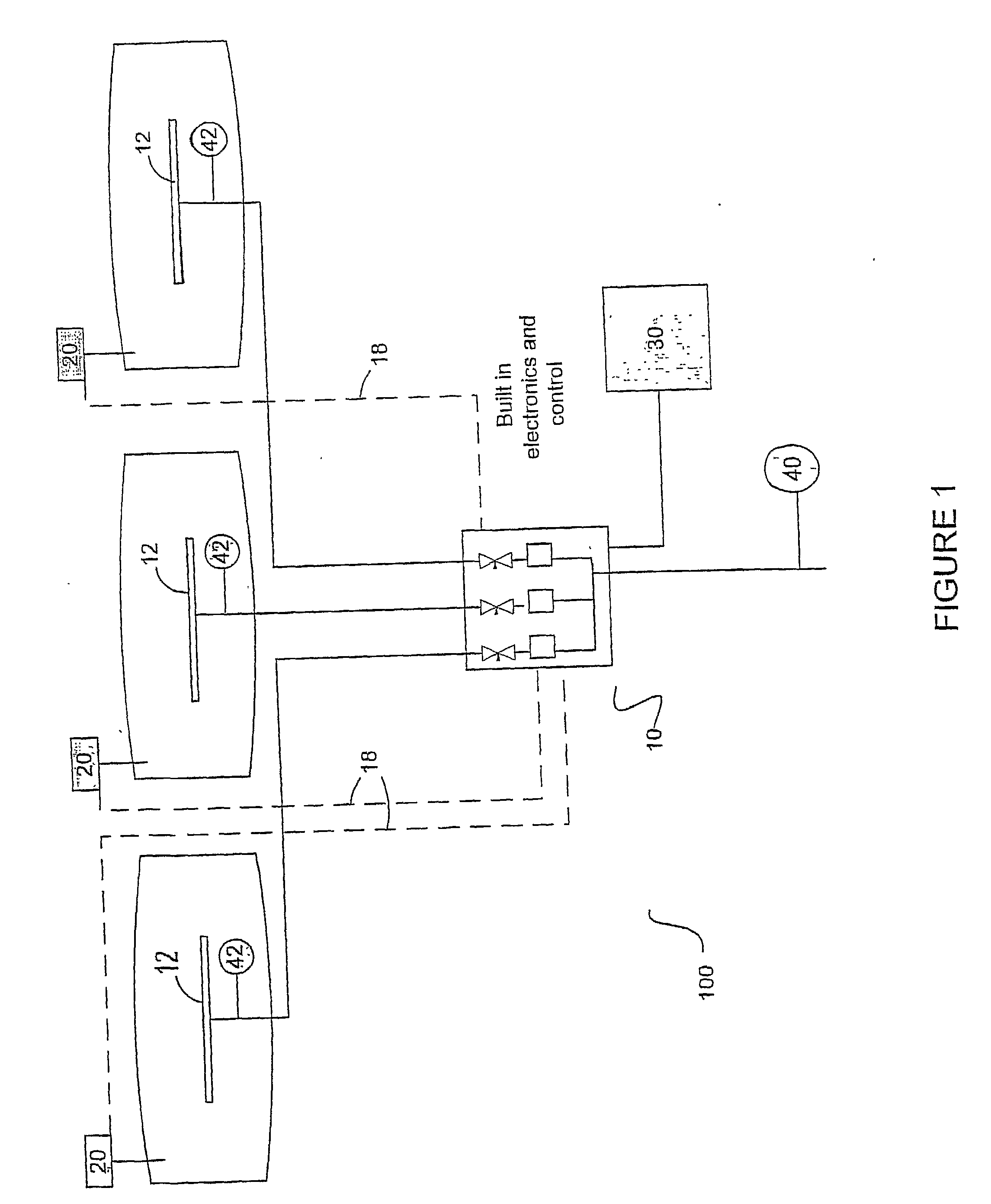
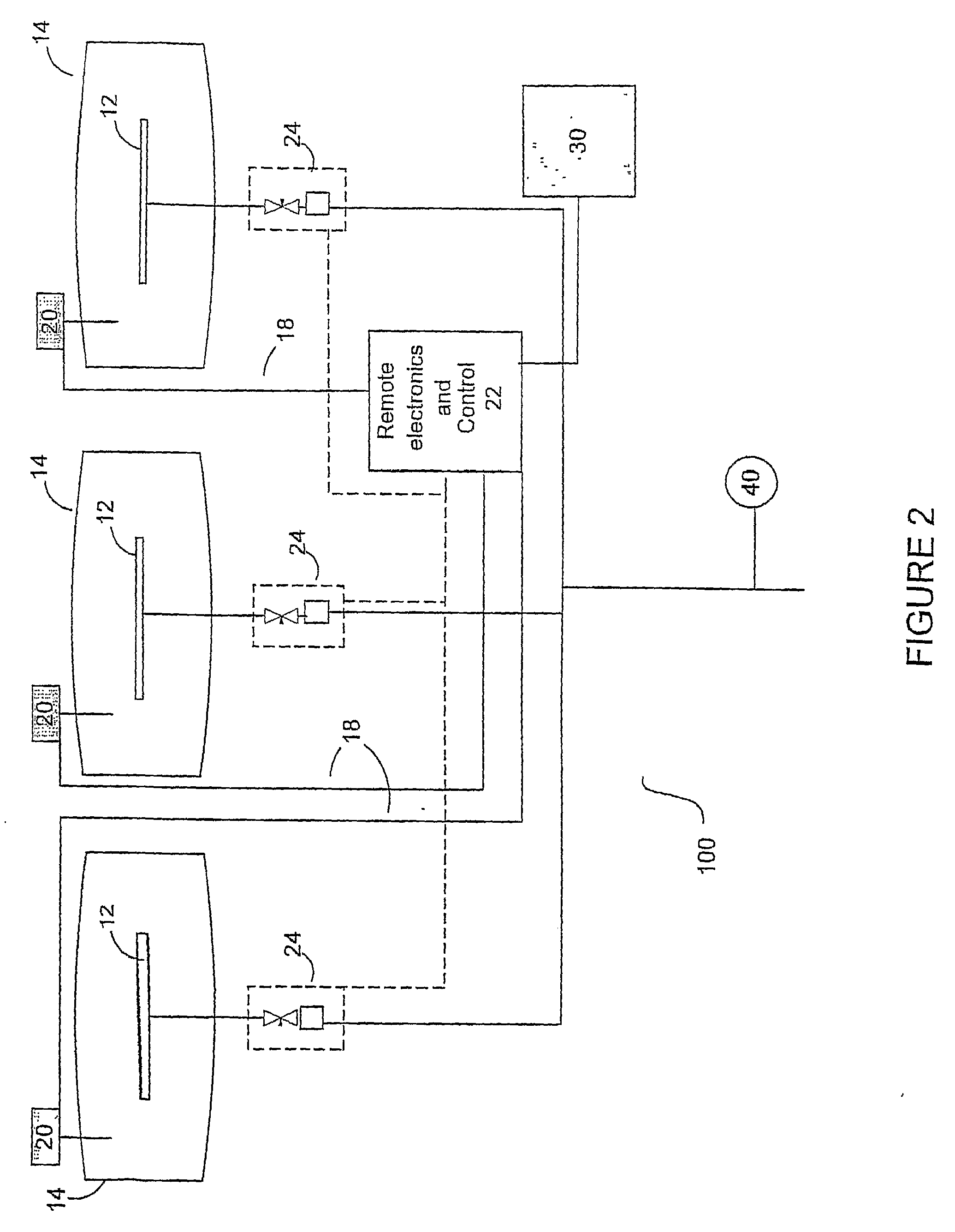
[0027] Attention is now directed to systems and methods for controlling the temperature of a wafer. These systems and methods may employ a bac...


PUM

PropertyMeasurementUnit
Temperatureaaaaaaaaaa
Pressureaaaaaaaaaa
Poweraaaaaaaaaa

Abstract

Systems and methods for controlling the temperature of a wafer are disclosed. These systems and methods may employ a back side wafer pressure control system (BSWPC) that includes subsystems and a controller operable in tandem to control the temperature of wafers in one or more process chambers. The subsystems may include mechanical components for controlling a flow of gas to the backside of a wafer while the controller may be utilized to control these mechanical components in order to control wafer temperature in a process chamber. Furthermore, embodiments of these systems and methods may also use a chiller in combination with the controller to provide both coarse and fine temperature control.

Description

RELATED APPLICATIONS AND PATENTS [0001] This application claims priority under 35 U.S.C. § 119 to U.S. Provisional Patent Application No. 60 / 619,414, by Kenneth E. Tinsley and Stuart A. Tison, filed Oct. 14, 2004 entitled “Method and System for Integrated Pressure and Temperature Control,” which is hereby fully incorporated by reference.TECHNICAL FIELD OF THE INVENTION [0002] The invention relates in general to methods and systems for controlling the temperature of a wafer in a processing environment, and more particularly, to systemized methods and systems for fine or coarse granularity temperature control. BACKGROUND OF THE INVENTION [0003] Modern manufacturing processes sometimes entail precise stoichiometric ratios during particular manufacturing phases. This is particularly true during semiconductor fabrication utilizing a process chamber. Because of the need for these precise stoichiometric ratios, the temperature of the object being manufactured (sometimes referred to as a wa...

Claims


Application Information

Patent Timeline
IPC IPC(8): G05D23/00
CPCH01L21/67248H01L21/67109
Inventor TINSLEY, KENNETH E.TISON, STUART A.
Owner BROOKS INSTRUMENT
Why Eureka
Try Eureka