

Apparatus for measuring dental occlusion
a technology for dental occlusion and measuring apparatus, which is applied in the field of apparatus for measuring dental occlusion, can solve the problems of inability to detect dental occlusion, inability to effectively use apparatus for making dentures, and undesirable for the lower jaw, and achieve the effect of accurate detection
- Summary
- Abstract
- Description
- Claims
- Application Information
AI Technical Summary
Benefits of technology
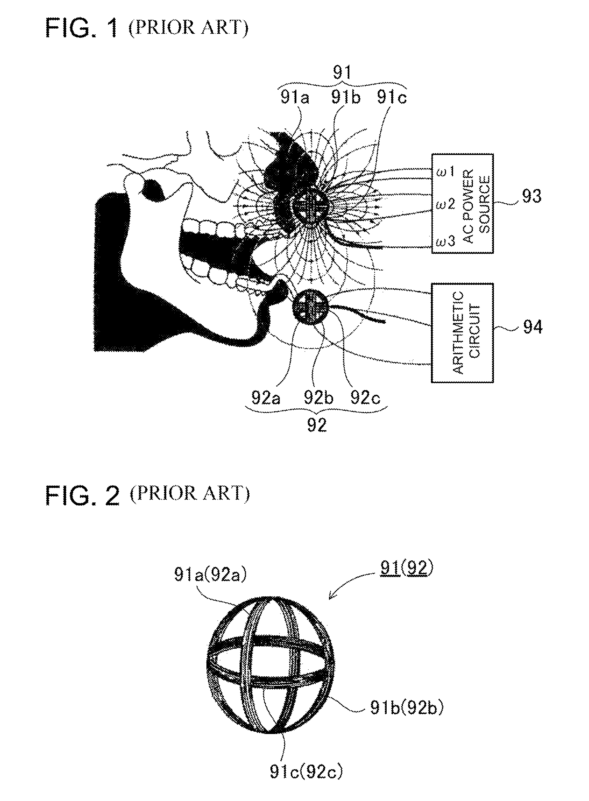
Problems solved by technology
Method used
Image

Examples
Embodiment Construction
[0086]Embodiments in accordance with the present invention shall be described hereinafter in conjunction with the accompanying drawings. It should be noted, however, that the ensuing description of embodiments is merely illustrative of the apparatus for measuring the dental occlusion only to embody technical ideas conceived in the present invention and that the invention shall in no way be specifically limited to the apparatus for measuring the dental occlusion as described below.
[0087]Further, in the present disclosure, for the purpose of better understanding the scope of the claims, the numerals corresponding with the members described in the embodiments are affixed to the members described in the “Claims” and the “Means to Solve the Problems”. It should be noted that the members described in the scope of claims are in no way limited to the members described in the embodiments.
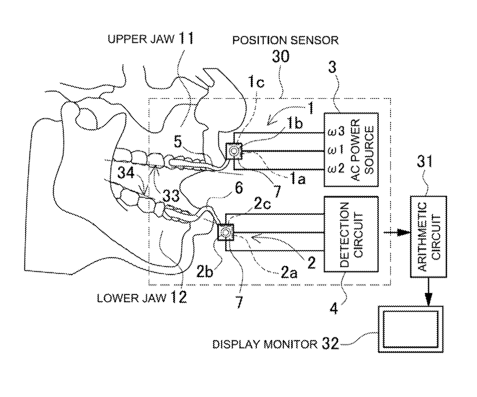
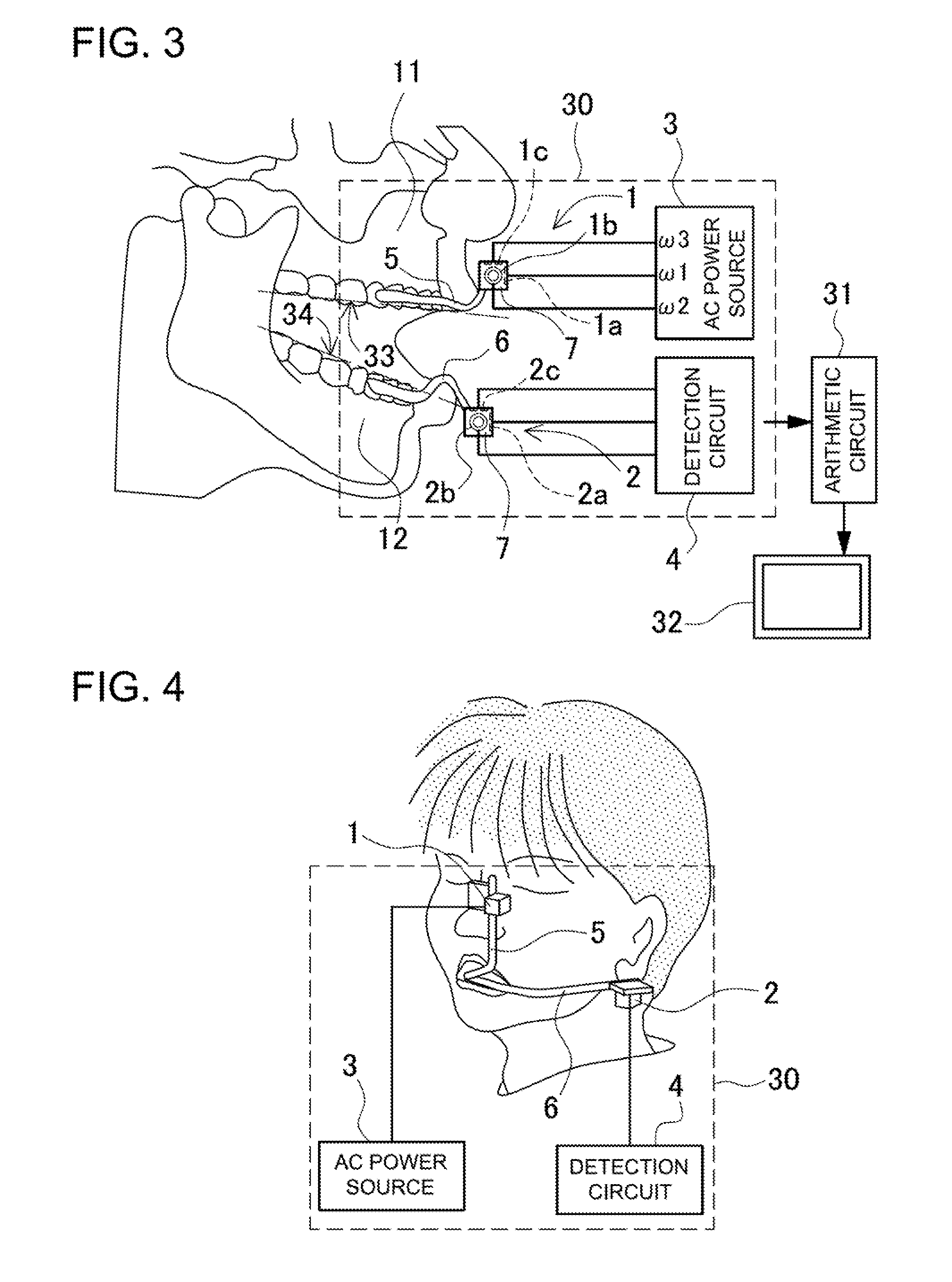
[0088]The apparatus for measuring the dental occlusion as shown in FIG. 3 includes: a position sensor 30 ...
PUM
 Abstract
Description
Claims
Application Information