
Control box for motor

a control box and motor technology, applied in the field of motors, can solve the problems of difficult disassembly, inconvenient use, and large installation inconvenience, and achieve the effects of improving the function of the invention, facilitating the switching between and facilitating the use of different input interface circuits

Active Publication Date: 2012-12-25
ZHONGSHAN BROAD OCEAN MOTOR MFG
View PDF12 Cites 12 Cited by
  • Summary
  • Abstract
  • Description
  • Claims
  • Application Information

AI Technical Summary

Benefits of technology

Enables users to select modes like constant speed, power, and torque, facilitates interface switching, and improves heat dissipation, making the motor more user-friendly and efficient in operation.

Problems solved by technology

However, there are several problems with structure of motors: 1) control functions thereof are comparatively simple, which makes them unable to meet requirements of users, and main control problems comprise: no select switch is set for users, and thus the users cannot select a constant speed mode, a constant power mode, a constant torque mode according to different requirements; and switching between input interface circuits cannot be facilitated according to types of control signals of a user control system, which brings about great inconvenience for the users; 2) structure thereof is unreasonable, control thereof is comparatively simple, and no communication interface is left, which makes it inconvenient to communicate with the outside world; 3) no debug window is disposed on the control box, and connection between a power line or a control line and a control circuit board is troublesome, parameters of electronic components cannot be adjusted, and an impeller is disposed at a shaft end of the motor, which makes it difficult to fix a rotating shaft during installation, and causes great inconvenience for installation; 4) since the power line and the control line extend from side wall of the control box, tightness thereof is not good enough, and installation and connection thereof are inconvenient; 5) the control circuit board is disposed in the control box, since space is small and the air does not flow therein, heat dissipation is a big problem, since power and heat dissipation of the pump motor are large, temperature raises quickly and becomes very high during operation, which causes that heat is difficult to be dissipated; and 6) no structure for fastening heat dissipation is disposed at the bottom of the control box.

Method used


Image

  • Control box for motor
  • Control box for motor
  • Control box for motor

Examples


Embodiment Construction

[0026]Further description of the invention will be given below in conjunction with specific embodiments and accompanying drawings.

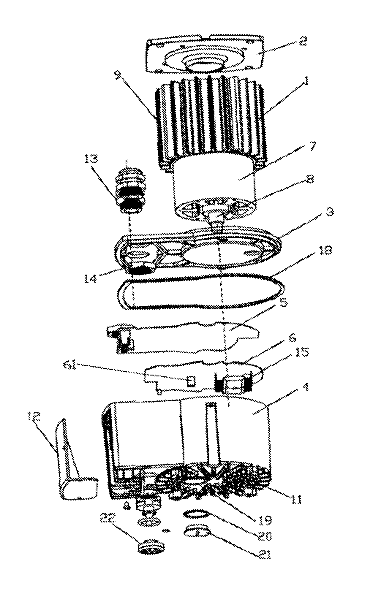
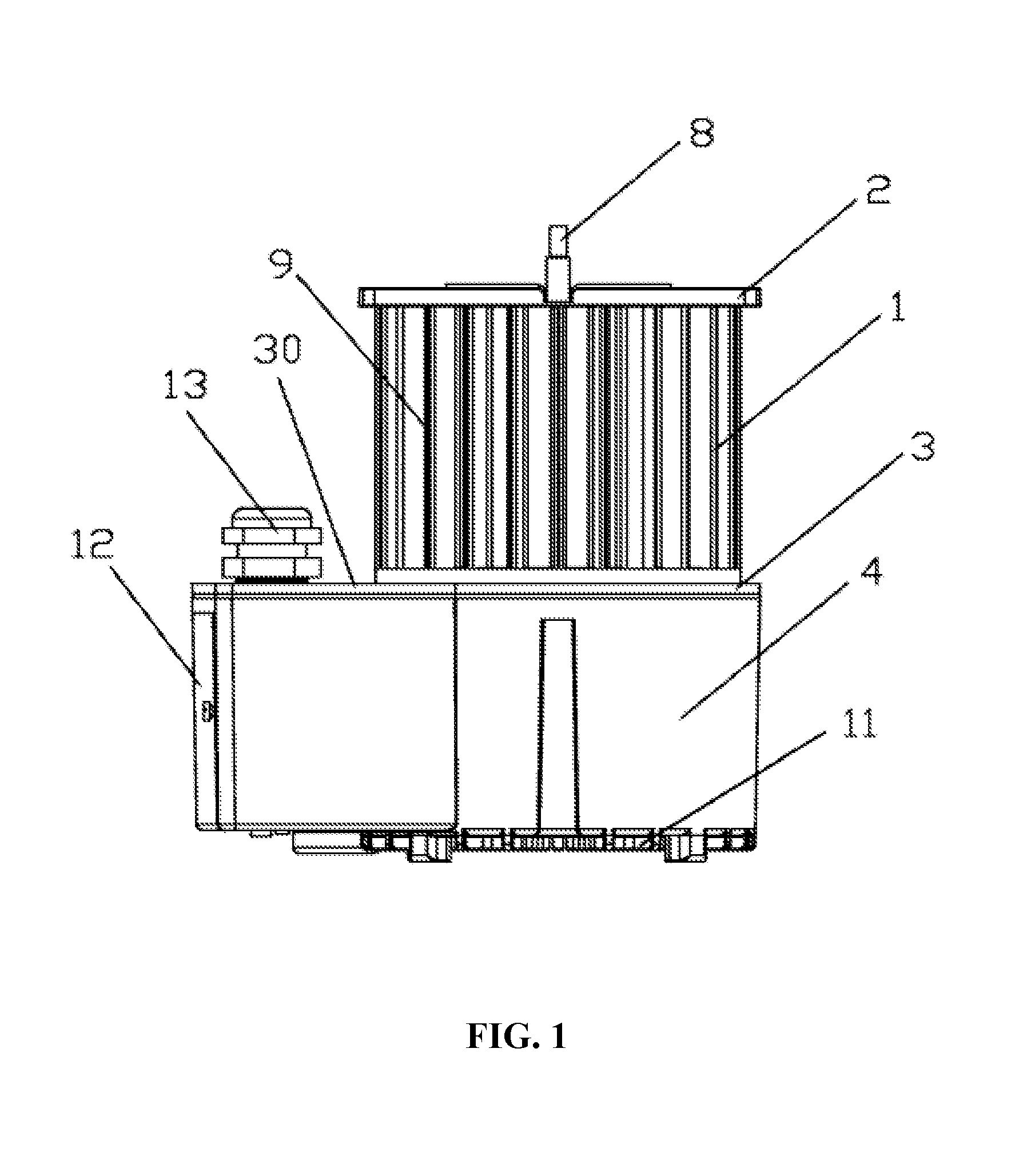
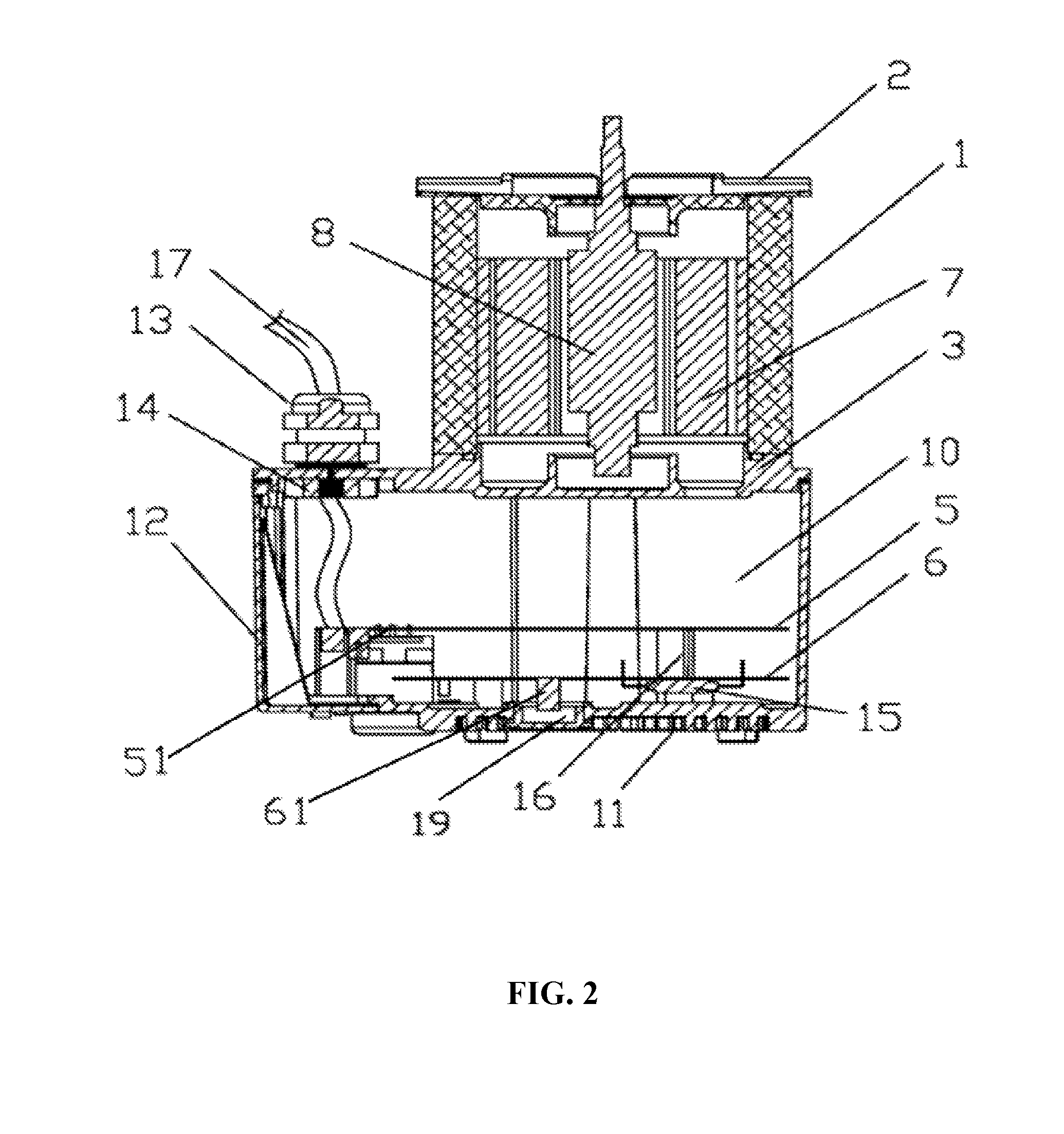
[0027]As shown in FIGS. 1-6, a motor of the invention comprises a body disposed at the top thereof, and a controller disposed at the bottom thereof. The body comprises a housing, a stator 7, and a rotor 8. The housing comprises an upper end cover 2, a metal case 1 with a heat dissipation fin 9, and a lower end cover 3. The stator 7 and the rotor 8 are disposed in the metal case 1, and the upper end cover 2 and the lower end cover 3 each has a bearing chamber for installing the rotor 8.

[0028]A debug window 23 is disposed on side wall or at the bottom of the control box 4, a sealing cover 12 is disposed on the debug window 23, the sealing cover 12 can be opened, and the control circuit board can be exposed for wire connection, adjustment of parameters of electronic components, and fixation of a rotating shaft according to requirements of users for installat...


PUM


Abstract

A motor, including a body, including a housing, a stator, and a rotor, and a controller, including a control box, and a control circuit board. The body is disposed at the top of the motor. The controller is disposed at the bottom of the motor. The control circuit board is disposed in the control box. A rotary dip switch is disposed at the bottom of the control box. The control circuit board includes a power board, and a control board. The rotary dip switch is electrically connected to the control board. The rotary dip switch controls different functions of the motor.

Description

CROSS-REFERENCE TO RELATED APPLICATIONS[0001]This application is a continuation of International Patent Application No. PCT / CN2010 / 070345 with an international filing date of Jan. 25, 2010, designating the United States, now pending, and further claims priority benefits to Chinese Patent Application No. 200920055048.7 filed on Apr. 16, 2009. The contents of all of the aforementioned applications, including any intervening amendments thereto, are incorporated herein by reference.BACKGROUND OF THE INVENTION[0002]1. Field of the Invention[0003]The invention relates to a motor.[0004]2. Description of the Related Art[0005]Nowadays, motors are widely used in various industries. However, there are several problems with structure of motors: 1) control functions thereof are comparatively simple, which makes them unable to meet requirements of users, and main control problems comprise: no select switch is set for users, and thus the users cannot select a constant speed mode, a constant power ...

Claims


Application Information

Patent Timeline
Patent Type & Authority Patents(United States)
IPC IPC(8): H02K5/04H02K11/00H02K5/22
CPCH02K11/0073H02K15/0006H02K11/33
Inventor TANG, SONGFAZHAO, YONG
Owner ZHONGSHAN BROAD OCEAN MOTOR MFG
Learn More