Wireless communication system, radio base station apparatus and radio terminal apparatus

a technology of radio base station and radio terminal, which is applied in the direction of multiplex communication, wireless commuication services, polarisation/directional diversity, etc., can solve the problems of low efficiency of communication and easy cqi error, and achieve the improvement of frequency utilization efficiency of mobile stations located at cell edges, high precision, and improved frequency utilization efficiency

Active Publication Date: 2012-12-25
HITACHI LTD
View PDF14 Cites 0 Cited by
  • Summary
  • Abstract
  • Description
  • Claims
  • Application Information

AI Technical Summary

Benefits of technology

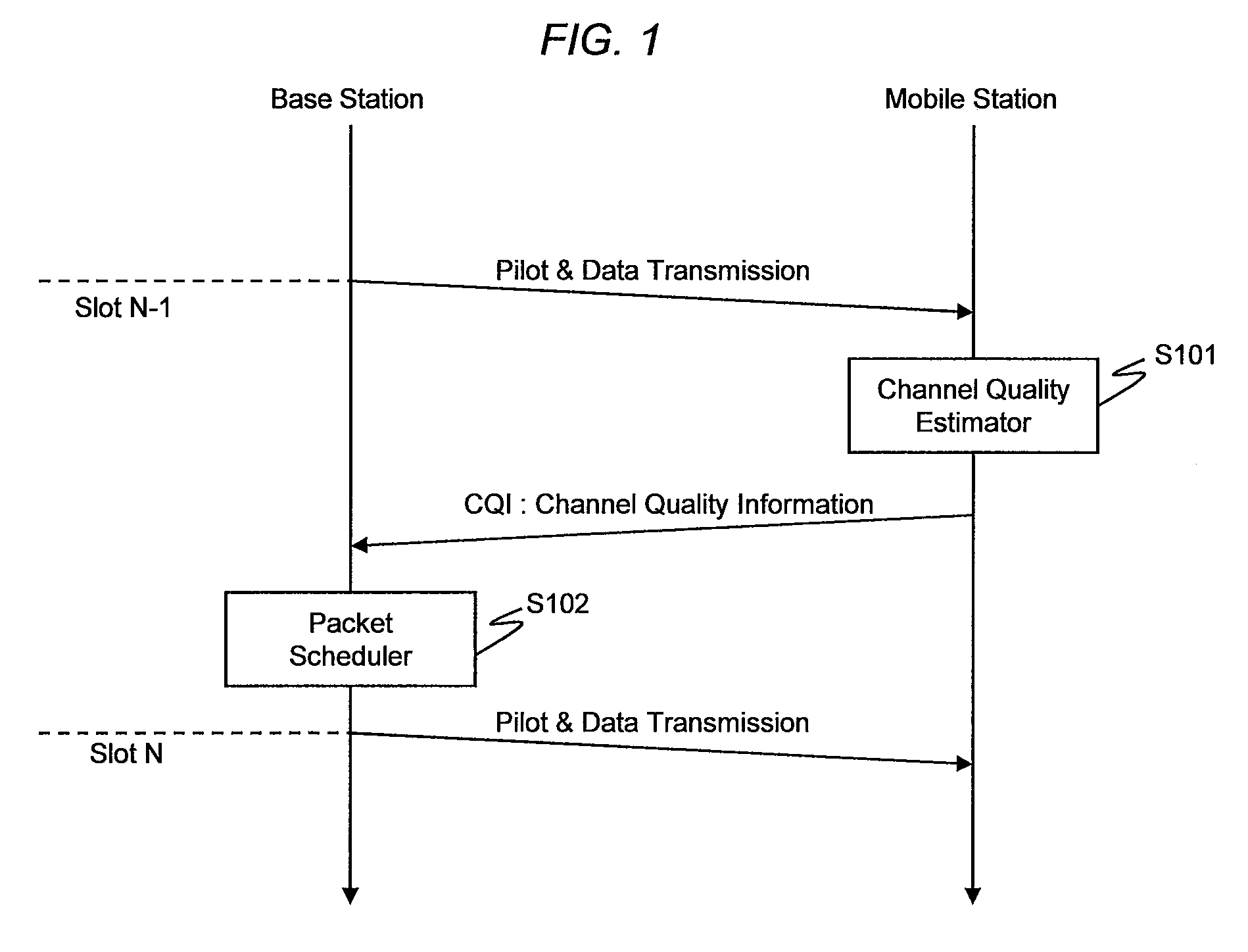
[0018]As a consequence, since the pilot and the directional beam of the data which are transmitted in the slot N are different from those transmitted in a slot N−1, an SINR estimated by the pilot of the slot N−1 is not corrected in the slot N. The object of this invention is to avoid lowering the frequency utilization efficiency due to the above-described SINR estimation error.
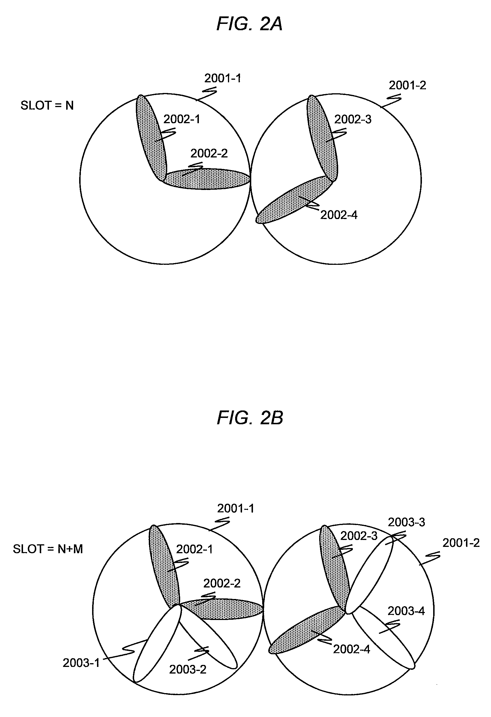
[0028]As a consequence, as shown in FIG. 2A, in order to satisfy the law of causality, at a time of a slot N, the directional beam output of the slot M+N is defined, an estimation pilot is output in this beam 2002, and the mobile station estimates a downlink communication quality to feed back the estimated downlink communication quality to the base station. As a result, since a transmission path quality of the slot M+N can be estimated at the time of the slot N, the above-described object can be achieved. It should also be noted that, in order to increase estimation precision of the communication qualities, it is desirable to multiplex the signal of the directional beam 2002 with the signal of the directional beam 2003 shown in FIG. 2B (by utilizing, for example, time division multiplexing, or frequency division multiplexing) within a slot in order that these signals do not interfere with each other.
[0035]According to this invention, the downlink communication quality containing also the intercell interference is correctly estimated, and hence the adaptive modulation of the downlink communication can be operated with higher precision, and thus the frequency utilization efficiency can be improved. Particularly, since the intercell interference power can be correctly estimated, the frequency utilization efficiency of the mobile station located at the cell edge can be improved.
[0036]In addition, according to this invention, the downlink communication qualities can be estimated correctly with respect to any of directional beam patterns which are generated by the smart antenna technology. As a consequence, both the merit achieved by the spatial multiplexing operation based upon the smart antenna technology, and the merit achieved by the high-precision adaptive modulating operation based upon the correct communication quality estimation can be utilized to the maximum extent, and hence the frequency utilization efficiency can be improved due to the multiplied effect of these merits.

Problems solved by technology

However, the base station and the mobile station perform the communications in the low efficiency under such a condition in which communications may be carried out in a high efficiency.
In order to avoid lowering of such a frequency utilization efficiency, it is an important challenge that the CQI is correctly estimated in the mobile station.
In a smart antenna base station, a CQI error may easily occur, as compared with that of a base station equipped with a sector antenna.

Method used


Image

  • Wireless communication system, radio base station apparatus and radio terminal apparatus
  • Wireless communication system, radio base station apparatus and radio terminal apparatus
  • Wireless communication system, radio base station apparatus and radio terminal apparatus

Examples


first embodiment

[0085]FIG. 8 represents a first embodiment mode related to an estimation directional beam decision, according to this invention.

[0086]In the first embodiment mode, a description will be made of an estimation directional beam decision in a case where the base station is a switched beam base station.

[0087]A beam selector 1101 selects a fixed beam which is utilized as an estimation directional pattern and a detection directional pattern succeeding to the estimation directional pattern by several time slots among the fixed beams held in a fixed beam buffer 1103 by the base station, and then, notifies a beam notification unit 1102 of a beam identification number thereof.

[0088]In order to select a beam direction, information held in the base station is read. Specifically, the various sorts of information are read from the queue buffer 1001a, the feedback buffer 1001b, and the DOA buffer 1001c. It should also be noted that reading of the above-described various information is not necessari...

second embodiment

[0093]FIG. 9 represents a second embodiment mode related to an estimation directional beam decision, according to this invention.

[0094]In the second embodiment mode, a description will be made of an estimation directional beam decision in a case where the base station is a base station which outputs an arbitrary directional beam pattern.

[0095]A direction decision unit 1104 decides both a beam direction and a null direction of a directional beam generated by a beam generator 1105 for every beam identification number, and then, notifies the beam generator 1105 of the decided beam and null directions. In order to decide a beam direction, information is held in the base station and then is read. Specifically, the various sorts of information are read from the queue buffer 1001a, the feedback buffer 1001b, and the DOA buffer 1001c.

[0096]Similarly to the first embodiment mode, it is conceivable that a difference may appear in frequency utilization efficiencies, depending upon direction d...


PUM


Abstract

A wireless communication system comprises radio base station apparatuses each of which transmits an estimation pilot in advance for estimating the quality of a downlink communication after a spatial signal processing performed after a time unified among the radio base station apparatuses; and radio terminal apparatuses each of which receives the estimation pilot to determine the quality of the downlink communication, thereby reporting the determined downlink communication quality to the radio base station apparatus via an uplink channel. The estimation pilot is transmitted at the same time and frequency established among the radio base station apparatuses by use of the same directivity beam as used for transmitting the data after the unified time.

Description

BACKGROUND OF THE INVENTION[0001]1. Technical Field[0002]This invention relates to a technology capable of increasing a frequency utilization efficiency by an adaptive modulation communication based upon a feedback of a downlink communication quality in a base station equipped with a smart antenna technology.[0003]2. Background Art[0004]Recently, smart antenna technology using array antennas has been practically used for base stations and access points (hereinafter, collectively referred to as base station) of wireless communication systems such as portable telephones and wireless LANs. The operating principle of the smart antenna technology is disclosed in, for instance, B. Widrow, et al.: “Adaptive Antenna Systems”, Proceedings IEEE, Vol. 55, No. 12, pages 2143 to 2159, December 1967. Base stations in which a plurality of terminals commonly utilize the same time and the same frequency and spatial multiplexing communications are performed based upon the smart antenna technology is ...

Claims


Application Information

Patent Timeline
Patent Type & Authority Patents(United States)
IPC IPC(8): H04W4/00H04B7/10H04W16/28H04W24/10H04W72/08H04W72/12
CPCH04B7/0617H04B7/0697H04W72/1231H04W24/00H04W16/28H04W72/542
Inventor FUJISHIMA, KENZABUROTAIRA, MASANORI
Owner HITACHI LTD
Why Eureka
Try Eureka