Evaluation of the feedback quality in communications systems

a communication system and feedback technology, applied in the field of measuring systems, can solve the problem of low cost of the measuring system and achieve the effect of low cos

Active Publication Date: 2012-12-25
ROHDE & SCHWARZ GMBH & CO KG
View PDF11 Cites 1 Cited by
  • Summary
  • Abstract
  • Description
  • Claims
  • Application Information

AI Technical Summary

Benefits of technology

[0006]The invention provides a measuring system and a measuring method whic

Problems solved by technology

The cost of the meas

Method used


Image

  • Evaluation of the feedback quality in communications systems
  • Evaluation of the feedback quality in communications systems
  • Evaluation of the feedback quality in communications systems

Examples


Embodiment Construction

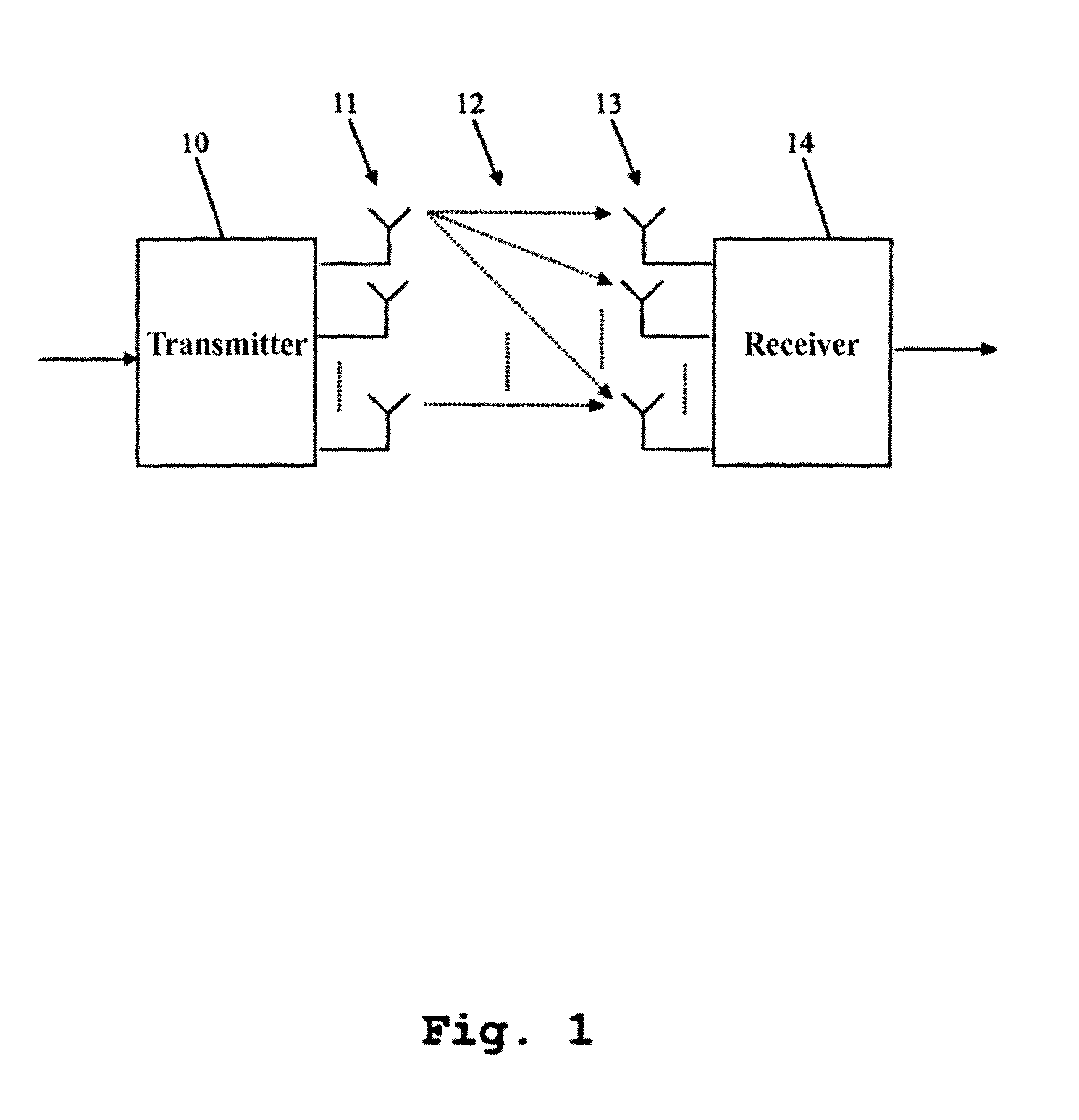
[0024]The structure and function of a MIMO communications system will first be explained with reference to FIG. 1. With reference to FIGS. 2-5, the structure and function of various exemplary embodiments of the measuring system according to the invention will then be explained. The presentation and description of identical elements in similar drawings has not been repeated in some cases.

[0025]FIG. 1 shows an exemplary communications system. The transmitter 10 is connected to several spatially-separate antennae 11. A receiver 14 is also connected to several spatially-separate antennae 13. The transmitter 10 transmits signals via the antennae 11. In this context, the signals are not necessarily identical. The signals are propagated over the propagation paths 12 and are received by the receivers 14 via the antennae 13. In this context, with N antennae 11 at the transmitter end and M antennae 13 at the receiver end, there are N*M propagation paths. By supplying the antennae 11 through t...


PUM


Abstract

A measuring system is used for testing a feedback signal transmitted by a communications device within a communications system. The measuring system comprises an antenna system and a measuring device. The measuring device transmits a signal to a communications device via the air interface and the antenna system. The communications device receives the signal and generates a feedback signal dependent upon transmission conditions of the signal, which it has determined, and transmits it to the measuring device. The measuring device measures the actual reception quality of the signal in the communications device.

Description

BACKGROUND OF THE INVENTION[0001]1. Field of the Invention[0002]The invention relates to a measuring system and a method for determining the quality of the feedback (feedback) of the received-signal quality transmitted by communications devices within communications systems, especially MIMO communications systems (Multiple-Input Multiple-Output communications systems).[0003]2. Related Technology[0004]In communications systems, such as UMTS or WiMax, the feedback transmitted by participating devices with reference to the channel quality is conventionally used for the adaptation of the transmission, for example, of the base station. For instance, in a closed-loop method, the pre-coding is modified in order to guarantee optimum reception at the terminal-device end. However, this method relies on as accurate an estimation of the transmission conditions or mobile-radio channel properties as possible at the receiver end. Although the participating devices are equipped with corresponding f...

Claims


Application Information

Patent Timeline
IPC IPC(8): H04B3/46H04B17/00H04Q1/20
CPCH04B17/24H04B17/21H04B7/0619H04B17/0085H04B17/0087
Inventor GESSNER, CHRISTINA
Owner ROHDE & SCHWARZ GMBH & CO KG
Why Eureka
Try Eureka