Anterior cervical staple

a cervical staple and anterior screw technology, applied in the field of surgical staples, can solve the problems of affecting the application of implants, affecting the quality of surgical implants, and affecting the patient's voice, and achieve the effects of strong and rigidity, reduced profile, and faster implant application

Active Publication Date: 2013-01-01
AFLATOON KAMRAN
View PDF41 Cites 18 Cited by
  • Summary
  • Abstract
  • Description
  • Claims
  • Application Information

AI Technical Summary

Benefits of technology

[0011]It is an object of the present invention to provide an anterior cervical staple that allows for a precise, small profile of fixation.
[0013]It is yet another object to provide a cervical staple that is strong and rigid yet lower profile.
[0014]Still another object is to provide an anterior cervical staple that is lightweight.
[0015]In accordance with the foregoing objects, the present invention comprises a surgical staple for the anterior approach that includes a plate with sharp-pointed projections positioned at each of four corners of the plate and extending perpendicularly there from for frictional insertion into pilot holes formed in the vertebrae, and a pair of circular apertures in the plate spaced along a centerline for insertion of bone screws. The plurality of projections further comprise four barbed and pointed projections that a surgeon may quickly tap into the bone, thereafter securing the staple with two smaller bone screws. This leads into a quicker implant application, less retraction as it may be done individually for each level and much stronger fixation than two screws alone.

Problems solved by technology

The typical screws are large and bulky.
There are benefits and drawback to both of these constructs.
Large plates and multiple screws offer a solid fixation but are bulky, use large screws, and require significant retraction for cases of multiple fixations which may lead into patients suffering from swallowing difficulties and possible changes in voice.
A variety of designs for spinal fixation devices have been proposed over the years although none have been entirely satisfactory.

Method used


Image

  • Anterior cervical staple
  • Anterior cervical staple
  • Anterior cervical staple

Examples


Embodiment Construction

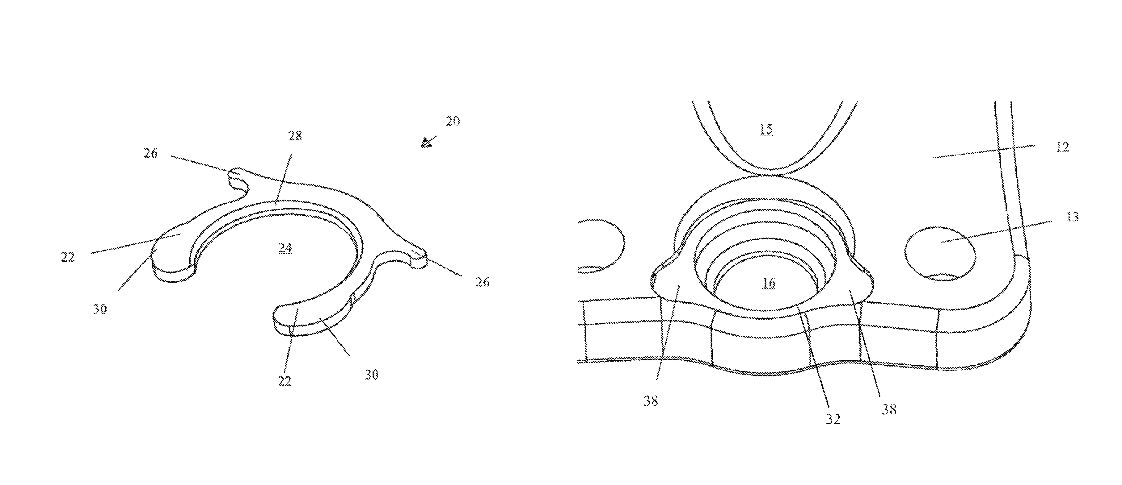
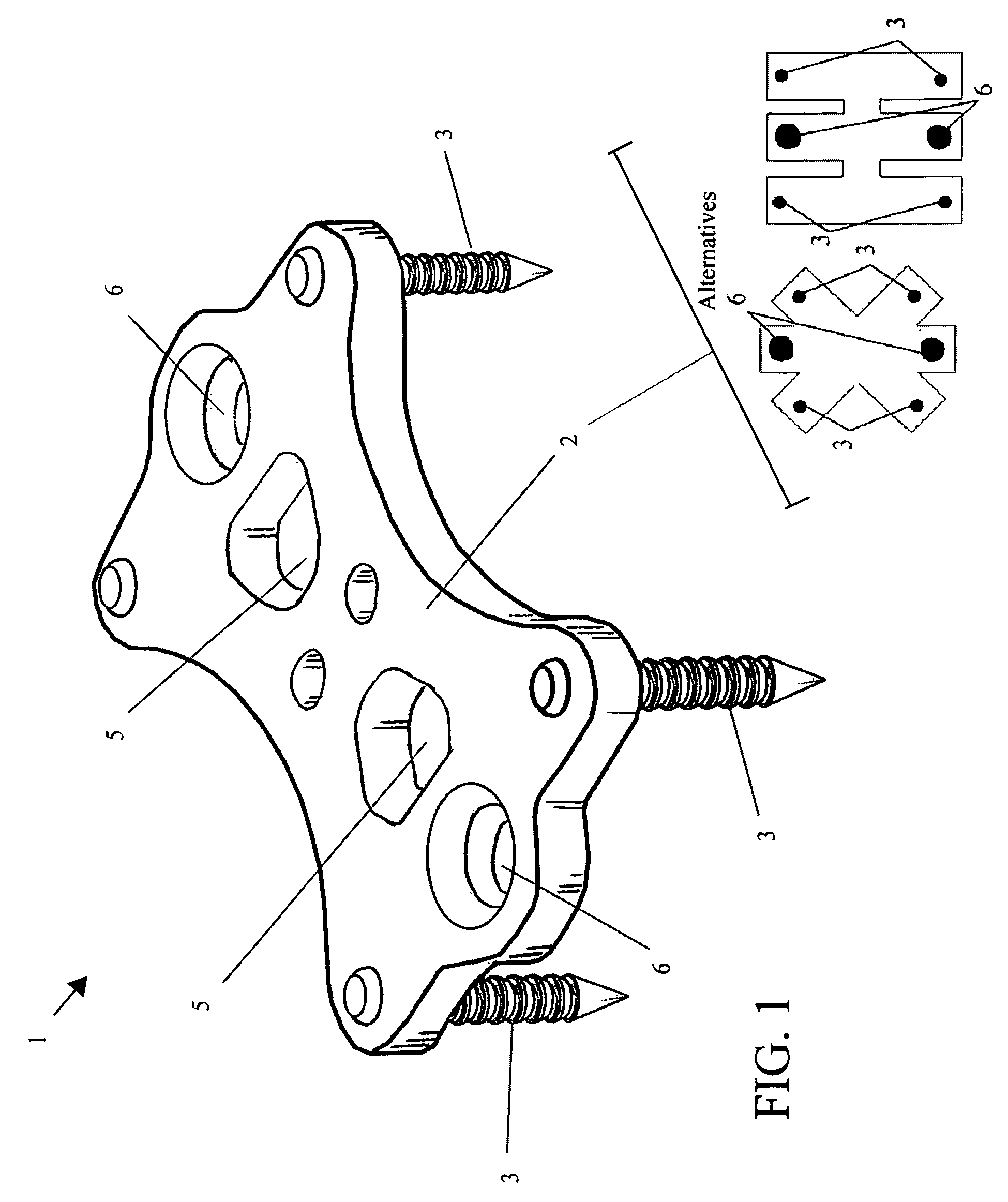
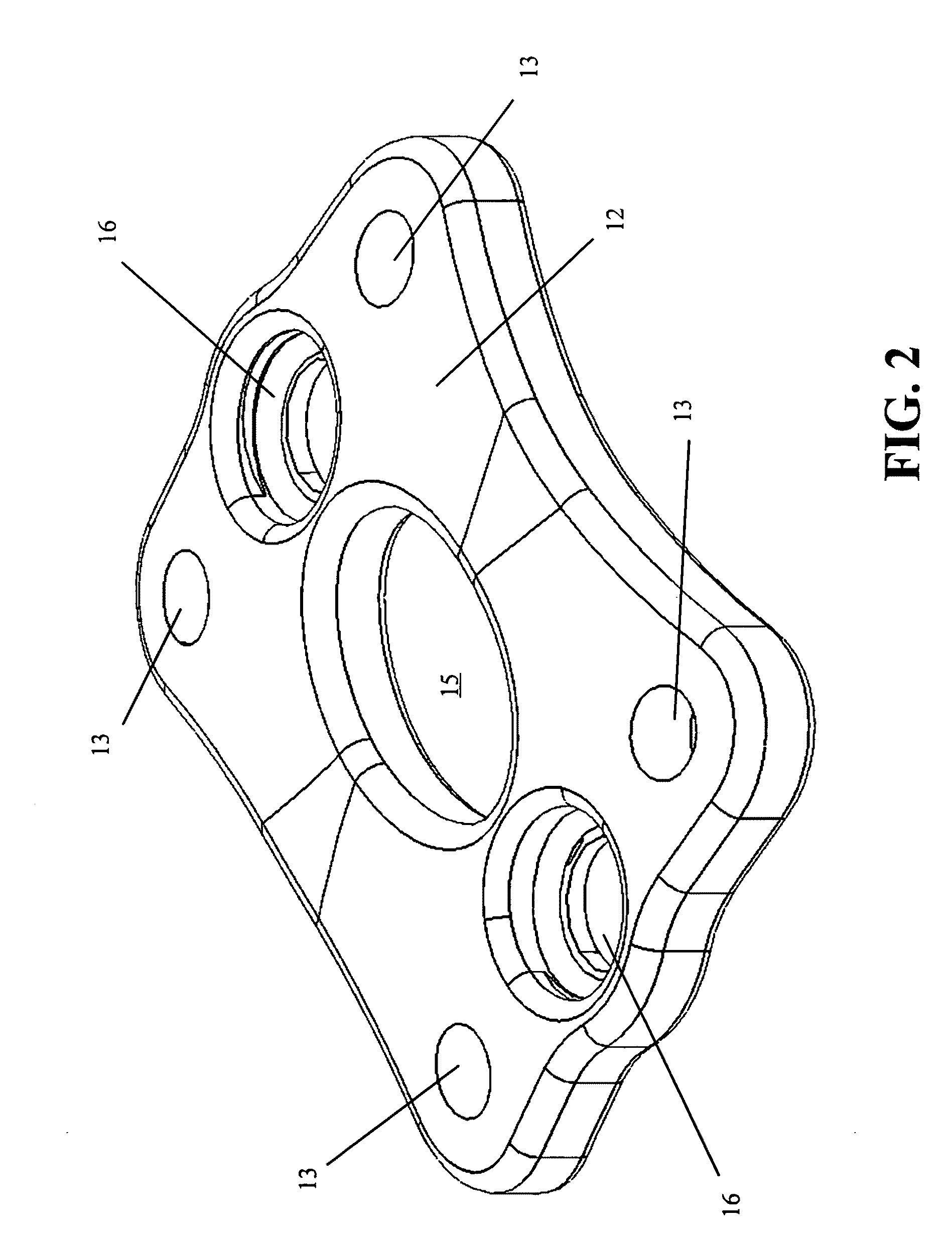
[0028]The present invention comprises a staple for anterior fusion. FIG. 1 is a front / oblique perspective view of an embodiment of the staple 1. The staple 1 as depicted in FIG. 1 includes a substantially planar plate 2 with a plurality of projections 3. The projections 3 are positioned at each of the four corners of the plate 2 and extend downwardly in a perpendicular direction from the bottom surface of the plate 2. The projections 3 may be separate components press-fit through holes in the plate 2 or may be integrally formed therewith. The projections 3 are preferably barbed (such as, for example, with concentric annular teeth as shown in FIG. 1) and terminate in a pointed distal end to facilitate their insertion into the vertebrae. The plurality of projections 3 provide for the staple 1 to be quickly hammered into the vertebrae V after a discectomy is done and bone graft is in place, as opposed to fixating the plate with four screws in a conventional manner.

[0029]The body of the...


PUM


Abstract

A surgical staple for discectomy by an anterior approach that comprises a plate with sharp-pointed projections positioned at each of four corners of the plate and extending perpendicularly there from for frictional insertion into pilot holes formed in the vertebrae, and a pair of circular apertures in the plate spaced along a centerline for insertion of bone screws. The plurality of projections may further comprise four barbed and pointed projections that a surgeon may quickly tap into the bone, thereafter securing the staple with two smaller bone screws. An Annular C shaped retention locking clip retains the bone screws and prevents counter-rotation and back out.

Description

CROSS-REFERENCE TO RELATED APPLICATIONS[0001]The present application derives priority from provisional application 60 / 965,471 filed on Aug. 20, 2007.BACKGROUND OF THE INVENTION[0002]1. Field of the invention[0003]The present invention relates to a surgical staple for discectomy by anterior approach to the cervical spine.[0004]2. Description of the Background[0005]Spinal stenosis is a medical condition in which the spinal canal narrows and compresses the spinal cord and nerves causing pain and neural degeneration. This is commonly due to spinal degeneration that naturally occurs with aging but can also be caused by spinal disc herniation (from trauma for example), osteoporosis, tumor or a variety of other causes. Stenosis may occur at any point along the spinal column but is more prevalent in the cervical and lumbar regions of the spine.[0006]Cervical discectomy is a surgical procedure for treating spinal stenosis and disc herniation in the cervical region. Removal of the interverteb...

Claims


Application Information

Patent Timeline
Patent Type & Authority Patents(United States)
IPC IPC(8): A61B17/80
CPCA61B17/7059A61B17/8042A61B17/809
Inventor AFLATOON, KAMRAN
Owner AFLATOON KAMRAN
Why Eureka
Try Eureka