
Passive optoceramics with cubic crystal structure, process for manufacturing the same and their uses

a technology of cubic crystal structure and optoceramics, applied in the field of optoceramics, can solve the problems of limited development of imaging optics, limited development of optical parameters, etc., and achieves the effects of low weight, low depth of installation space, and new imaging properties

Inactive Publication Date: 2013-01-01
SCHOTT AG
View PDF9 Cites 2 Cited by
  • Summary
  • Abstract
  • Description
  • Claims
  • Application Information

AI Technical Summary

Benefits of technology

[0038]A diffractive optical element (DOE) in the sense of the present invention is an element comprising at least one surface, which surface comprises structures in the size range of the wavelength of the electromagnetic radiation, which structures implement optically effective functions. These structures are for example holographic grates or holograms implementing optical functions or a Fresnel zone plate. Those structures have high refractive effectiveness over their whole cross section.
[0039]It is the object of the present invention to provide optoceramic material with high refractive index and / or high Abbe number and / or an excellent, special relative partial dispersion, which properties cannot be achieved with conventional glasses, single crystal material or other polycrystalline ceramics or materials.
[0040]According to another aspect of the present invention the claimed material family has high variability in the sense of substitution of metal ions of different valency so that optical properties can be varied in wide ranges. Furthermore, a cost-effective production of the optoceramic material is possible.
[0043]With the target compositions described herein it is possible to provide an optoceramic optical element that can be used with a reduced surface angle while improving imaging behavior.
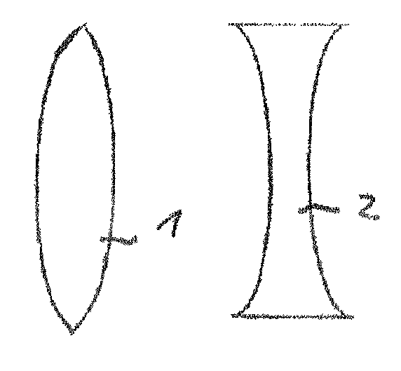
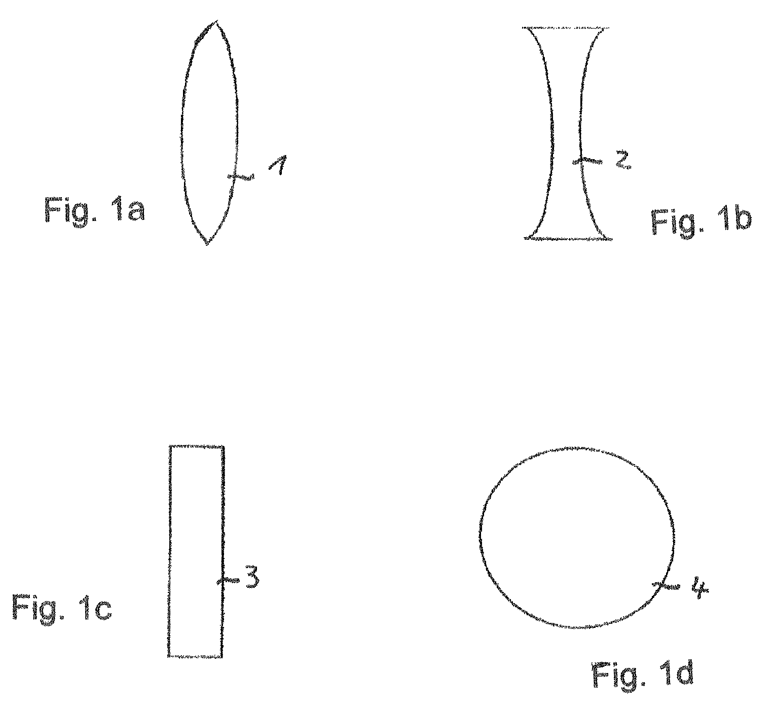
[0065]According to another aspect of the present invention an optical imaging system with lenses is provided, said system comprises at least two different transparent materials, wherein at least one lens is manufactured from an optoceramic as explained above. The invention is based on the insight that by application of two different transparent lens materials within an optical imaging system, like for example an objective, novel imaging properties can be provided. Especially the possibility of achromatisation of the optical imaging system is made possible with a comparatively low number of refractive optical elements, which effect could not be achieved by application of conventional glass types.
[0066]An example is the application of only three refractive optical elements for construction of a compact objective with approximately apochromatic imaging properties. In total, the present invention makes it possible to provide optical imaging systems for correction of chromatic aberrations with very low weight, low depth of installation space and low costs, which systems are compact when compared to multi-lens systems according to the state of the art.

Problems solved by technology

Similarly, a distinction between optoceramics and conventional ceramics are the high densities of optoceramics which cannot be achieved in conventional ceramics.
Today, development of imaging optics is limited by optical parameters of the available material.
More precisely, glasses with refractive indices between about 1.9 and about 2.2 and Abbe numbers in the range of from about 30 to about 40 tend to be unstable so that it is very difficult to manufacture such glasses in considerable amounts and sufficient quality.
The production of single crystals with known crystal growing techniques, however, is very expensive especially for high melting components, because of the very expensive breeding crucible material; further, this method is subject to limitations with respect to chemical compositions.
Furthermore, crystals cannot be produced in a near-net-shape or near-net-format manner, resulting in significant post-processing effort.
The production of single crystals is, as indicated above, very expensive and does not render manufacture of larger optical elements possible.
Although polycrystalline ceramics are obtainable in a wide range of compositions, they usually show insufficient optical quality, especially as far as homogeneity of refractive index and transmission is concerned.
The position of YAG in the Abbe diagram or Pg,F-diagram (nd=1.83, Abbe number=52.8; Pg,F=0.558; delta Pg,F=0.0031), which is not exotic enough and does not suffice for most applications, is a disadvantage of YAG for passive linear optical applications.
The YAG system is disadvantageous because, although chemical variability is high, the structure only accepts trivalent cations.
The possibilities of variation (tuning) of optical properties which are, besides other factors, influenced by the UV band gap structure, are therefore not sufficient for many purposes.
However, ceramics comprising such barium-containing phases with perovskite structure show insufficient optical imaging quality.
This results from the tendency of many perovskites to form distorted ferro-electrical crystal structures and thus loose their optical isotropy.
This inter alia leads to an undesired birefringence of the crystals from which the ceramic is made.
Furthermore, transmission in the blue spectral region (wavelength around 380 nm) is insufficient.
Only such ceramics are obtained that show transparencies of 70% at a sample thickness of <1 mm, which is too low for optical applications.
These active, i.e. light emitting, lanthanum compounds are not suitable for the desired application as passive optical elements.
Klimin, et al, in “Physics of Solid State”, Vol. 47, No. 8, 2005, describes single crystal material and polycrystalline compounds, however does not address optical grade transparency of any polycrystalline material.
Polycrystalline material is in the form of pressed powder that is slightly consolidated at quite low temperatures not higher than 1400° C. This procedure does not and cannot result in a material with sufficient optical properties.
Although the optoceramics described in this reference have cubic pyrochlore structures they are rich in A2O3 component, which leads to optical deficiencies.

Method used


Image

  • Passive optoceramics with cubic crystal structure, process for manufacturing the same and their uses
  • Passive optoceramics with cubic crystal structure, process for manufacturing the same and their uses

Examples


Embodiment Construction

[0075]As described in the following, the optoceramics according to the present invention are transparent materials with refractive indexes nd above or equal to about 1.90, preferably between about 2.0 and about 2.7, particularly preferred between about 2.1 and about 2.7. Most preferred is a refractive index of above 2.25 and even more preferred above 2.30. An Abbe number concurrently is in the range of from about 10 to about 45, preferably between about 10 and 40, particularly preferred between about 12 and 35. This facilitates novel combinations of materials for use in achromatisation of lens systems.

[0076]All of the claimed optoceramics are mixed systems, i.e. they consist of at least two cations of different valency (positions of A, B, D). The stoichiometry of the oxidic powder batch or of the finished compound powder must hence be exactly oriented to this stoichiometry. Ideally, the compositions only differ in the range of up to 10 mol %, ideally up to 5 mol % from the target co...


PUM

PropertyMeasurementUnit
Abbe numberaaaaaaaaaa

Abstract

The optoceramics are transparent to visible light and / or infrared radiation. The optoceramics each consist of a crystal matrix, i.e. of polycrystalline material, wherein at least 95% by weight, preferably at least 98% by weight, of the single crystallites have a cubic pyrochlore or a fluorite structure. Refractive, transmissive or diffractive optical elements made with the optoceramics, their uses and an optical imaging system comprising at least one of the optical elements are also disclosed. Methods of manufacturing the optoceramics are described.

Description

CROSS-REFERENCE[0001]The invention described and claimed herein below is also described in European Patent Application 09 157 992.8, filed Mar. 31, 2009 in Europe. The aforesaid German Patent Application, whose subject matter is incorporated herein by reference thereto, provides the basis for a claim of priority of invention for the invention claimed herein below under 35 U.S.C. 119 (a)-(d).BACKGROUND OF THE INVENTION[0002]1. The Field of the Invention[0003]The present invention relates to optoceramics, a process for their production and their uses. The invention also relates to refractive, transmissive or diffractive optical elements manufactured from these optoceramics as well as imaging optics. These optoceramics and optical elements are permeable to visible light and / or infrared radiation. The optoceramics consist of a crystal network, i.e. they constitute poly-crystalline material that is composed of a multitude of individual crystals.[0004]2. Description of the Related Art[000...

Claims


Application Information

Patent Timeline
Patent Type & Authority Patents(United States)
IPC IPC(8): C04B35/50C04B35/00C04B35/51C04B35/48C04B35/49B28B3/00B28B1/00
CPCB82Y30/00C04B35/462C04B35/486C04B35/49C04B35/495C04B35/6263C04B35/638C04B35/6455C04B2235/3224C04B2235/3225C04B2235/3227C04B2235/3232C04B2235/3244C04B2235/3251C04B2235/3287C04B2235/3293C04B2235/5454C04B2235/549C04B2235/602C04B2235/6027C04B2235/604C04B2235/6562C04B2235/6567C04B2235/658C04B2235/6581C04B2235/6582C04B2235/661C04B2235/663C04B2235/762C04B2235/9653
Inventor MENKE, YVONNEPEUCHERT, ULRICHIKESUE, AKIO
Owner SCHOTT AG
Learn More