Optoceramics, optical elements manufactured thereof and their use as well as imaging optics

a technology of optical elements and optical components, applied in the field of optoceramics and refractive, transmissive or diffractive optical elements, can solve the problems of limited development of imaging optics, difficult to manufacture such glasses in high quantities and sufficient quality, and may not achieve high densities of optoceramics, etc., to achieve low cost, low weight, and low depth of installation space

Inactive Publication Date: 2010-05-04
SCHOTT AG
View PDF12 Cites 8 Cited by
  • Summary
  • Abstract
  • Description
  • Claims
  • Application Information

AI Technical Summary

Benefits of technology

[0050]According to another aspect of the present invention an optical imaging system with lenses is provided, said system comprising at least two different transparent materials, wherein at least one lens is manufactured from an optoceramic as explained above. The invention thus starts from the insight that by application of two differently transparent lens materials within an optical imaging system, like for example an objective, novel imaging properties can be provided. Especially the possibility of achromatisation of the optical imaging system is made possible with a comparatively l

Problems solved by technology

Similarly, within conventional ceramics the high densities of optoceramics may not be achieved.
Today, development of imaging optics is limited by optical parameters of the available material.
More precisely, glasses with refractive indices between about 1.9 and about 2.2 and an Abbe number in the range of from about 30 to about 40 tend to be unstable so that it is very difficult to manufacture such glasses in high amounts and sufficient quality.
The production of single crystals with the known crystal breeding techniques, however, is very expensive especially for high melting components, because of the very expensive breeding crucible material; further this method is subject to limitations with respect to chemical compositions.
Furthermore, crystals cannot be produced in a near-netshape or near-netformat manner, resulting in significant postprocessing effort.
The production of single crystals is, as indicated above, very expensive and does not render manufacture of larger optical elements possible.
Although polycrystalline ceramics are obtainable in a wide range of compositions, they usually show insufficient optical quality, especially as far as homogeneity of refractive index and transmission is concerned.
Disadvantages of YAG for passive linear optical applications are the position in the Abbe diagram or Pg,F-diagram (nd=1.83, Abbe number=52.8; Pg,F=0.558; delta Pg,F=0.0031), which is not “exotically” enough and does not suffice for most applications.
The YAG system a

Method used


Image

  • Optoceramics, optical elements manufactured thereof and their use as well as imaging optics
  • Optoceramics, optical elements manufactured thereof and their use as well as imaging optics

Examples


Embodiment Construction

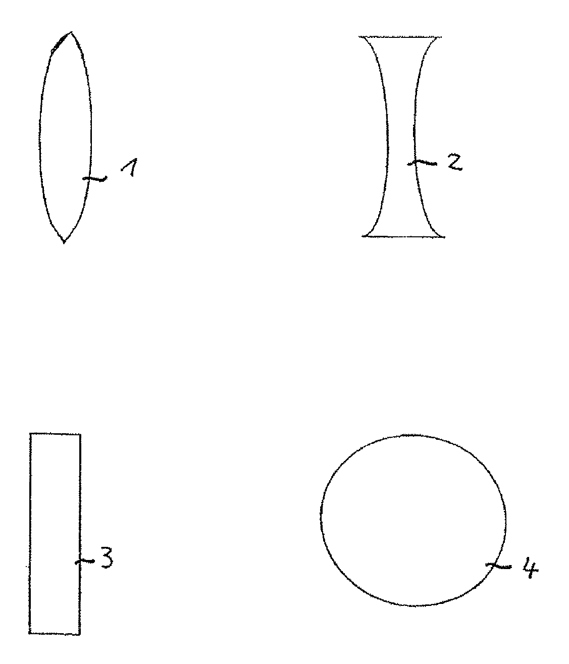
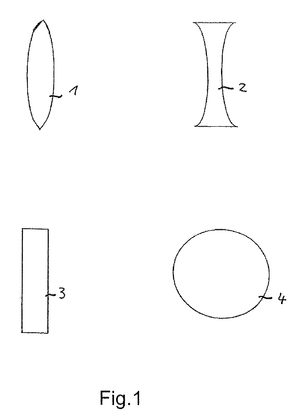
[0058]The four examples of transmissive and / or refractive optical elements according to the present invention shown in FIG. 1 comprise a biconvex lens 1, a bio-concave lens 2, a purely transmissive optical element 3 and a spherical lens 4. The indicated lenses 1, 2 and 4 are preferred applications of the optoceramics according to the present invention with regard to the optical elements.

[0059]As described in the following, the optoceramics according to the present invention are transparent materials with refractive indexes nd above or equal to about 1.90, preferably between about 2.0 and about 2.7, particularly preferred between about 2.1 and about 2.7. Most preferred is a refractive index of above 2.25 and even more preferred above 2.30. An Abbe number concurrently is in the range of from about 10 to about 45, preferably between about 10 and 40, particularly preferred between about 12 and 35. This facilitates novel combinations of materials for use in achromatisation of lens system...


PUM

PropertyMeasurementUnit
Lengthaaaaaaaaaa
Fractionaaaaaaaaaa
Fractionaaaaaaaaaa

Abstract

The transparent polycrystalline optoceramic has single crystallites and at least 95 percent by weight of the single crystallites have a cubic pyrochlore or fluorite structure. The optoceramic is composed of an oxide of stoichiometry:
A2+xByDzE7
wherein 0<x<1, 0<y<2, 0<z<1.6 and 3x+4y+5z=8; wherein A is at least one trivalent rare earth cation; B is at least one tetravalent cation; D is at least one pentavalent cation; and E comprises at least one divalent anion. Refractive, diffractive or transmissive optical elements are made with these optoceramics.

Description

BACKGROUND OF THE INVENTION[0001]The present invention refers to optoceramics and refractive, transmissive or diffractive optical elements manufactured thereof their use as well as imaging optics. These optoceramics and optical elements are permeable to visible light and / or infrared radiation. The optoceramics consist of a crystal network, i.e. of polycrystalline material.[0002]An optoceramic according to the present invention is understood to be highly transparent material that is essentially single phase, polycrystalline and based on an oxide. Optoceramics are thus a special subdivision of ceramics. “Single phase” in this context is understood to mean that at least more than 95% by weight of the material, preferably at least 97% by weight, further preferred 99% by weight and most preferred 99.5 to 99.9% by weight of the material are present in the form of crystals of the desired composition. The individual crystals are arranged densely and, relative to the theoretical density, the...

Claims


Application Information

Patent Timeline
IPC IPC(8): G02B3/00C03C10/00
CPCG02B1/02Y10S501/90
Inventor PEUCHERT, ULRICHMENKE, YVONNE
Owner SCHOTT AG
Why Eureka
Try Eureka