Optical limiting using plasmonically enhancing nanoparticles

a technology of optical limiters and nanoparticles, applied in the field of laser irradiation, can solve the problems of reducing the efficiency of optical limiters, and molecule environmental instability, so as to prevent the transmission of incident light, improve the efficiency of optical limiters, and improve the effect of optical limiter performan

Active Publication Date: 2013-01-01
MASSACHUSETTS INST OF TECH
View PDF23 Cites 9 Cited by
  • Summary
  • Abstract
  • Description
  • Claims
  • Application Information

AI Technical Summary

Benefits of technology

[0008]In further embodiments, the device may include an alloy including at least one material selected from the group consisting of silver, gold, aluminum, indium and copper. The transparent medium may include a material selected from the group consisting of a polymer and a glass. The plurality of nanoparticles may include at least two different types of nanoparticles. The device may include a patterning of at least two different types of nanoparticles; and may include a pixel array comprising at least two different types of nanoparticles. The device may be sufficiently robust to be used more than once to protect the object from the incident light.
[0009]In another embodiment according to the invention, there is provided a method of protecting an object from incident light. The method comprises the step of exposing a device, positioned between the incident light and the object, to incident light of a wavelength in the visible, infrared or ultraviolet spectrum and of an intensity exceeding a threshold intensity, thereby at least substantially preventing transmission of the incident light above the threshold intensity through the device to the object. The device includes a plurality of nanoparticles of a metallic material including free electrons that undergo collective oscillations when exposed to the incident light at the wavelength in the visible, infrared or ultraviolet spectrum. The plurality of nanoparticles of the metallic material includes a plurality of nanoparticles of a non-spherical particle geometry. The plurality of nanoparticles of the metallic material are embedded in a structurally rigid transparent medium. The device is exposed to the incident light to thereby enhance a local electric field inside the surfaces of the plurality of nanoparticles of the non-spherical particle geometry to cause the plurality of nanoparticles of the non-spherical particle geometry to absorb the energy of the incident light above the threshold intensity and thereby at least substantially prevent transmission of the incident light above the threshold intensity through the device to the object. The method further comprises the step of exposing the device to incident light of an intensity not exceeding the threshold intensity, thereby at least substantially transmitting the incident light below the threshold intensity through the device to the object.
[0012]An embodiment according to the invention is of utility in protecting an object from incident light having a wavelength in the visible, infrared or ultraviolet spectrum. For example, the incident light may have an intensity exceeding a threshold intensity; and an embodiment according to the invention finds utility in at least substantially preventing transmission of the incident light when its intensity is above the threshold intensity while at least substantially transmitting the incident light when its intensity is below the threshold intensity. An embodiment according to the invention provides advantages over non-varying optical protection devices by adequately blocking intense radiation, but without being opaque during normal use. Further, an embodiment according to the invention provides advantages over narrowband devices by providing protection over a broad range of incident wavelengths and incident angles. Further, an embodiment according to the invention provides advantages of sensitivity, i.e., their transition from transparency to opaqueness may occur at eye-safe or equipment-safe incident intensities; advantages in having a high enough dynamic range that the transmitted intensity is “clamped” at eye-safe or equipment-safe levels even when the incident intensity varies by orders of magnitude; advantages in having a fast response time, on the scale of nanoseconds or less; and advantages in recovering their transparency quickly after the threat is over. Further, an embodiment according to the invention provides the advantages of insensitivity to the polarization of incident light, a wide acceptance angle, simplicity, environment stability, and the ability not to be damaged by high laser intensities.

Problems solved by technology

However, in order for such sunglasses to provide adequate blocking of intense radiation, they would have to be too opaque to be useful to the wearer.
Third, for many applications optical limiters should have a fast response time, on the scale of nanoseconds or less.
However, these molecules are often environmentally unstable, or they can be damaged by very high laser intensities.
Even more importantly, according to published papers the incident intensities required to induce changes in transmission are still several orders of magnitude too high (10-100 mJ / cm2), even in the most sensitive optical limiters.
Until now nanoparticles have not been considered as serious alternatives to organic molecule limiters, because their reported photosensitivity has been no better, and often worse than that of the organic optical limiters: 100-1000 mJ / cm2 have been required to induce a significant increase in absorption.

Method used


Image

  • Optical limiting using plasmonically enhancing nanoparticles
  • Optical limiting using plasmonically enhancing nanoparticles
  • Optical limiting using plasmonically enhancing nanoparticles

Examples


experiment 1

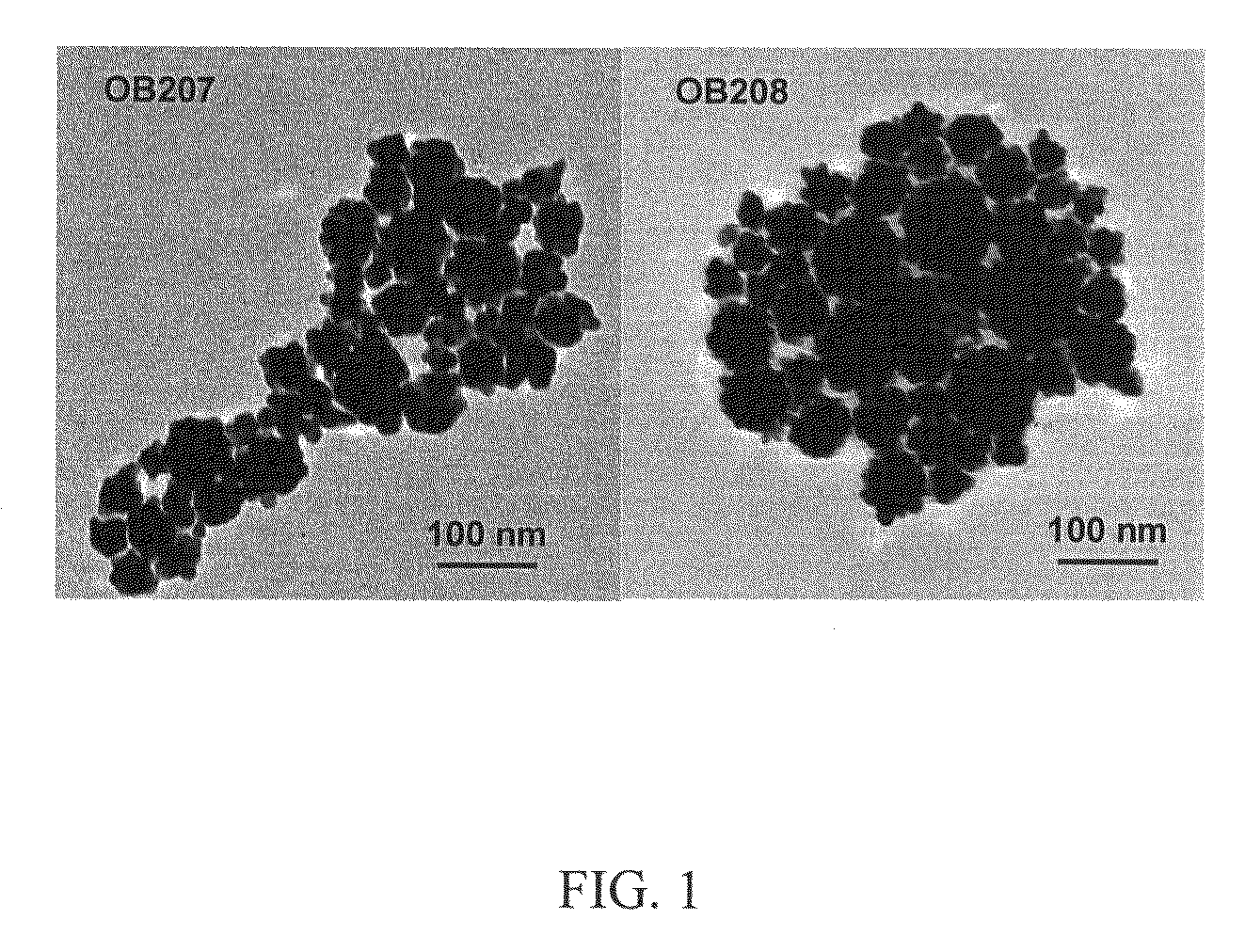
Nanoparticle Sample Preparation

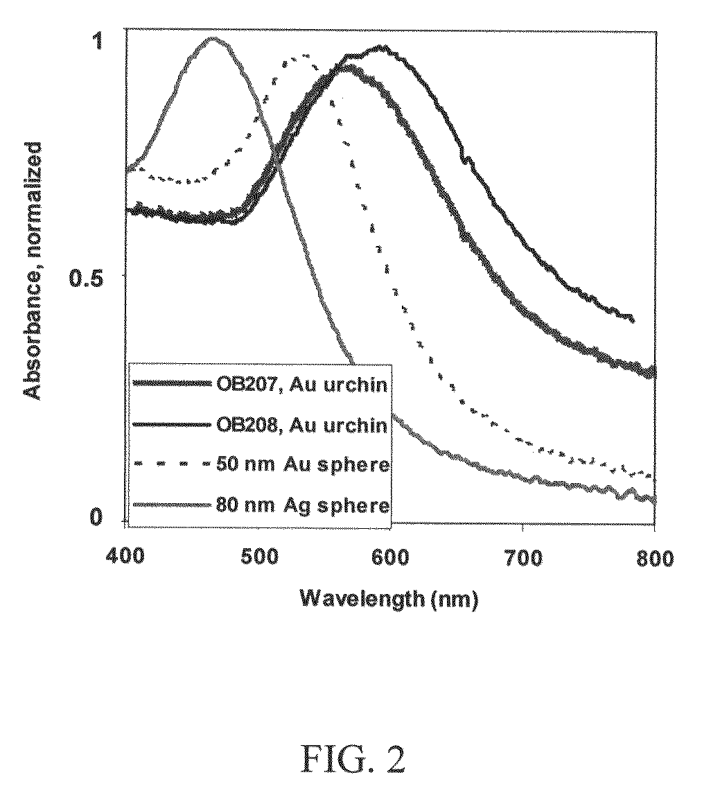
[0039]Aqueous-based nanoparticle solutions were used in experiments described herein, although it will be understood that other nanoparticle preparations may be used. Commercial Ag and Au nanospheres were obtained from BBI Corporation (distributed by Ted Pella) in nominal sizes varying from 20 nm diameter to 80 nm diameter. Solution concentrations were provided by the manufacturer and varied from 1011 to 1010 sols / cm3, depending on particle size. Nanoparticle solutions were diluted using deionized water as needed. Table 1 shows the concentration of all of the nanomaterials used for optical limiting measurements.

[0040]

TABLE 1Description of nanoparticles used in opticallimiting experiments and their concentrationConcentration usedNanoparticle Description(particles / cm3)80 nm Ag sphere, BBI1 × 10950 nm Au sphere, BBI2.6 × 1010 OB208 Au urchin, specially5 × 109synthesizedOB207 Au urchin, specially5 × 109synthesized

[0041]Au nanourchins were prepared using th...

experiment 2

Optical Limiting Measurement

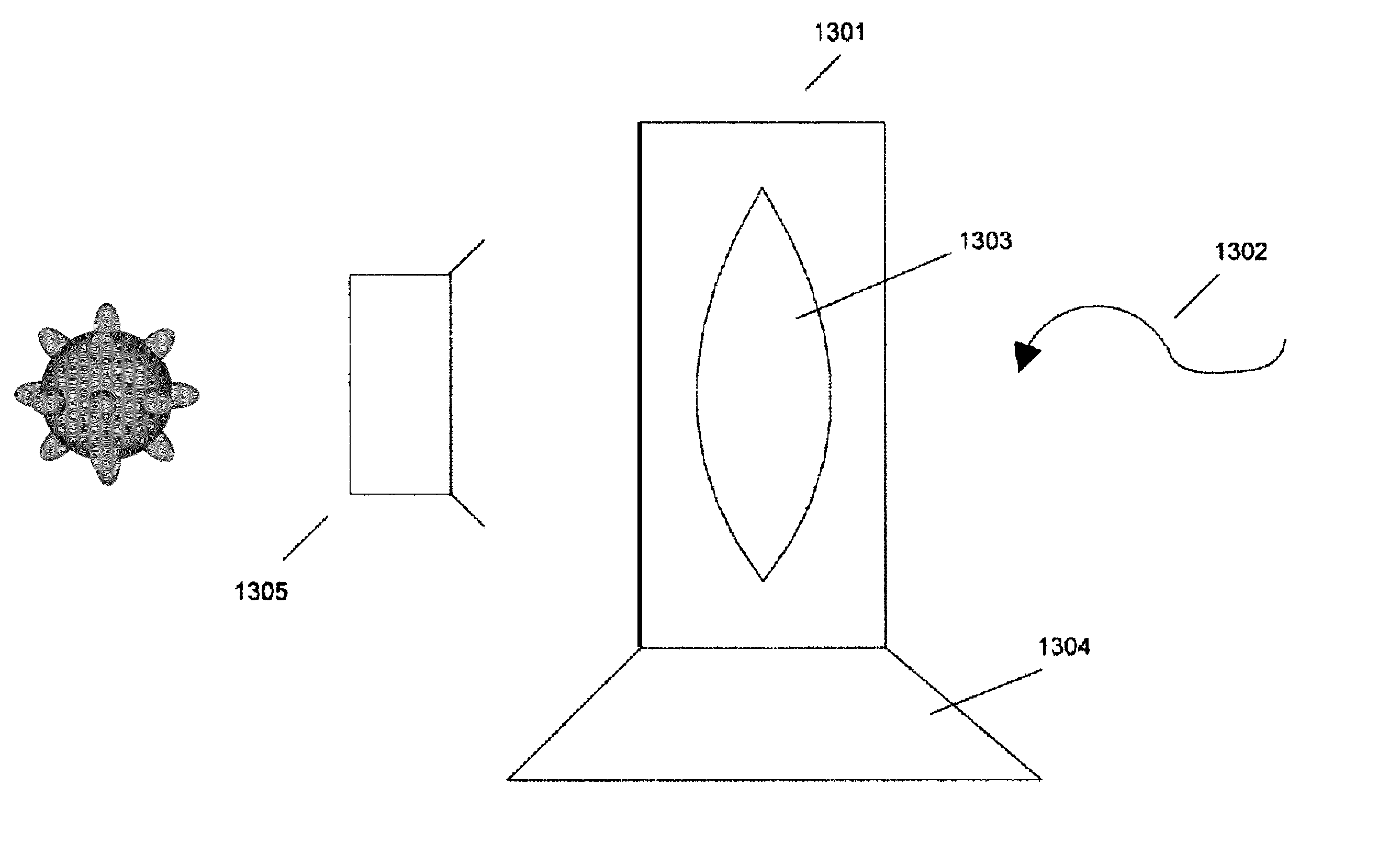
[0045]For the optical limiting characterization, we have chosen the Z-scan method described in M. Sheik-Bahae, A. A. Said, and E. W. Van Stryland, “High-sensitivity, single-beam n2 measurements,” Opt. Lett. 14, 955-957 (1989). In this technique, a thin sample is placed in a focused beam, where the intensity varies along the optical axis (Z-axis), and the transmission is recorded as a function of Z-position. Changes in transmission are then analyzed in terms of the sample's intensity-dependent optical properties, including the real and imaginary parts of the nonlinear index, the latter being related to two-photon absorption (see also further discussion below).

[0046]FIG. 3 is an experimental schematic of a Z-scan optical limiting setup used in experiments conducted in accordance with an embodiment of the invention. The laser source is a Continuum EX Plus OPO system which produces tunable radiation from near-IR down to 215 nm. For the purpose of this study, ...


PUM

PropertyMeasurementUnit
diameteraaaaaaaaaa
diameteraaaaaaaaaa
wavelengthsaaaaaaaaaa

Abstract

There is provided an optical limiter device for protecting an object from incident light having a wavelength in the visible, infrared or ultraviolet spectrum. The device comprises a plurality of nanoparticles of a metallic material including free electrons that undergo collective oscillations when exposed to the incident light. The plurality of nanoparticles of the metallic material include a plurality of nanoparticles of a non-spherical particle geometry, which may include a geometry having a plurality of sharp protrusions on a spherical body. The metallic material may include gold, silver, aluminum, indium or copper. The device further comprises a structurally rigid transparent medium in which the plurality of nanoparticles of the metallic material are embedded; and a mechanical support mounting the transparent medium between the incident light and the object.

Description

GOVERNMENT SUPPORT[0001]The invention was supported, in whole or in part, under United States Air Force contract number FA8721-05-C-0002, program number 1-9442. The Government has certain rights in the invention.BACKGROUND OF THE INVENTION[0002]Since the invention of laser irradiation, there has been a need for the protection of photosensitive objects from the intense light generated by lasers. Laser exposure may either be accidental, such as that from a portable range-finding device, or it may be deliberate, such as that from a hostile action. The protection is required for human eyes as well as for sensitive optical equipment, such as specialized cameras. In the case of eye protection, the maximum allowable energy or power incident on the eye has been quantified by the American National Standard for Safe Use of Lasers (Laser Institute of America, ANSI Z136.1-2007), and it depends on the laser wavelength and pulse duration. For example, for lasers in the visible (400-700 nm) and pu...

Claims


Application Information

Patent Timeline
Patent Type & Authority Patents(United States)
IPC IPC(8): G02B5/22B82Y20/00
CPCG02B5/008G02B5/22B82Y20/00
Inventor LIBERMAN, VLADIMIRROTHSCHILD, MORDECHAI
Owner MASSACHUSETTS INST OF TECH
Why Eureka
Try Eureka