
Device address assignment in a bus cascade system

a technology of device address and cascade system, which is applied in the direction of data conversion, instruments, computing, etc., can solve the problems of adding time and cost to the manufacturing process

Active Publication Date: 2013-01-01
O2 MICRO INT LTD
View PDF55 Cites 7 Cited by
  • Summary
  • Abstract
  • Description
  • Claims
  • Application Information

AI Technical Summary

Benefits of technology

The patent text describes a method of manufacturing devices without setting individual addresses, which helps reduce costs and speeds up the process. These devices can be assembled together without needing to manually set addresses, and the addresses can be assigned automatically. This reduces the number of ports needed and further lowers costs for devices implemented in integrated circuitry.

Problems solved by technology

Providing unique addresses at manufacturing can be done but adds time and cost to the manufacturing process.

Method used


Image

  • Device address assignment in a bus cascade system
  • Device address assignment in a bus cascade system
  • Device address assignment in a bus cascade system

Examples


Embodiment Construction

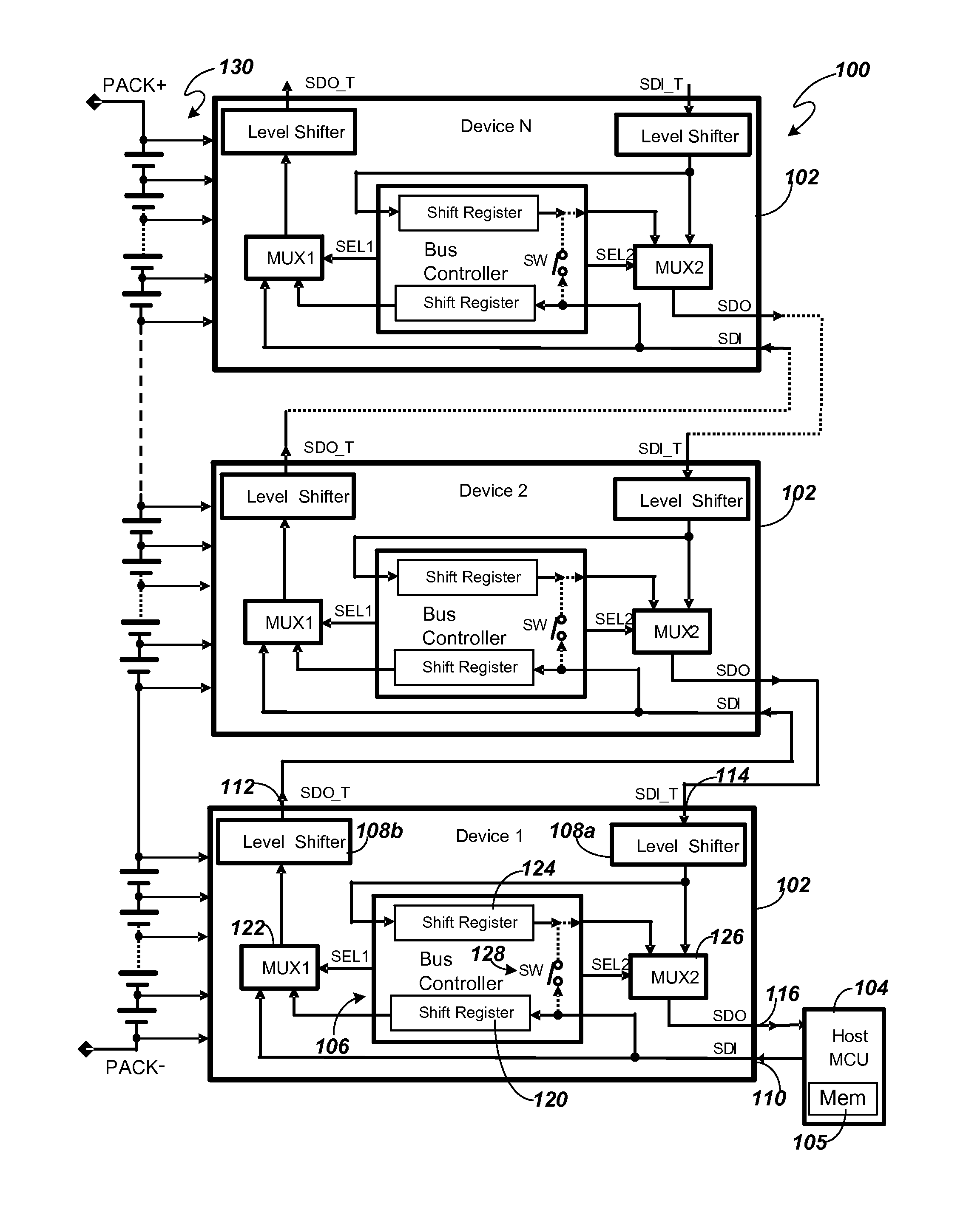
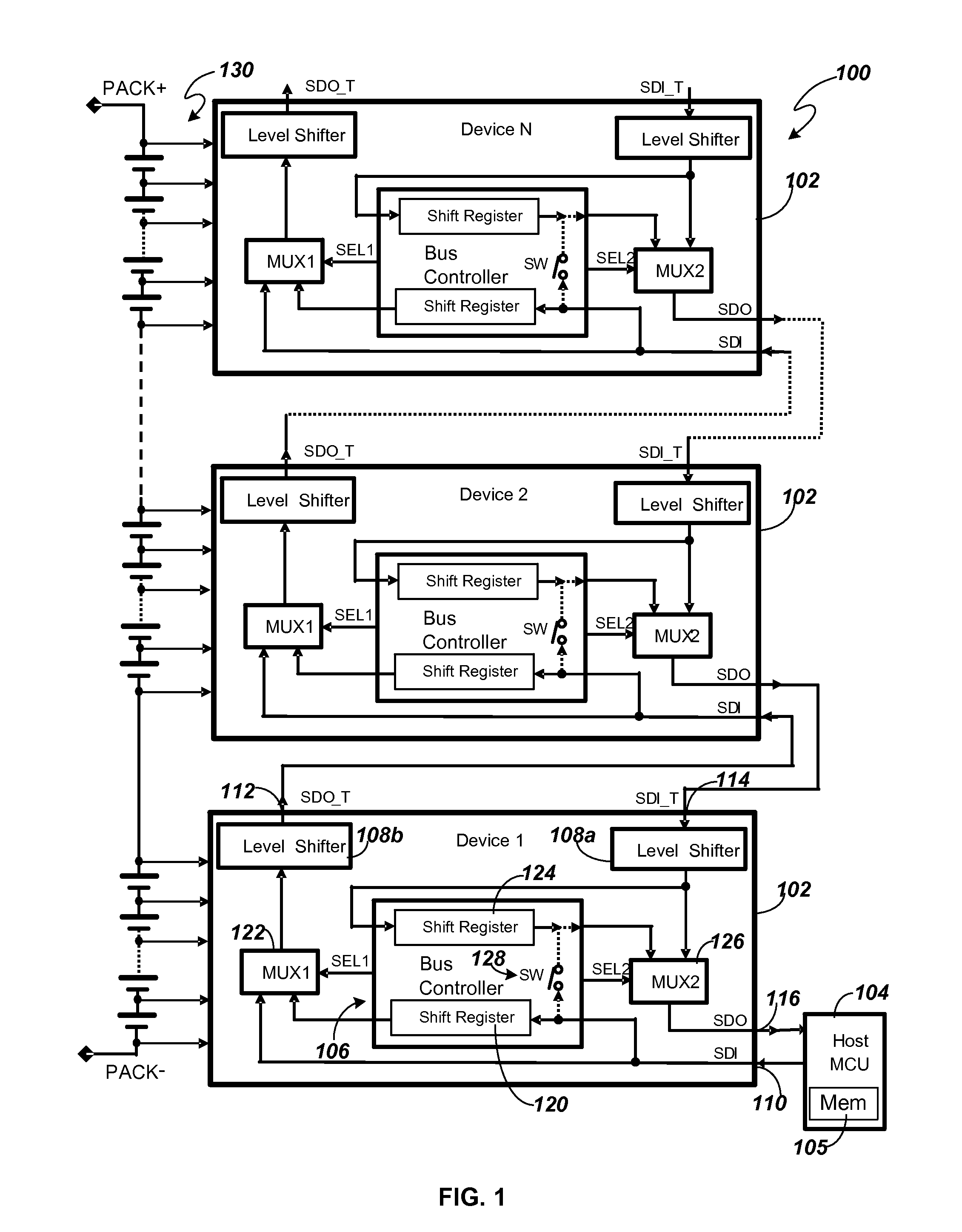
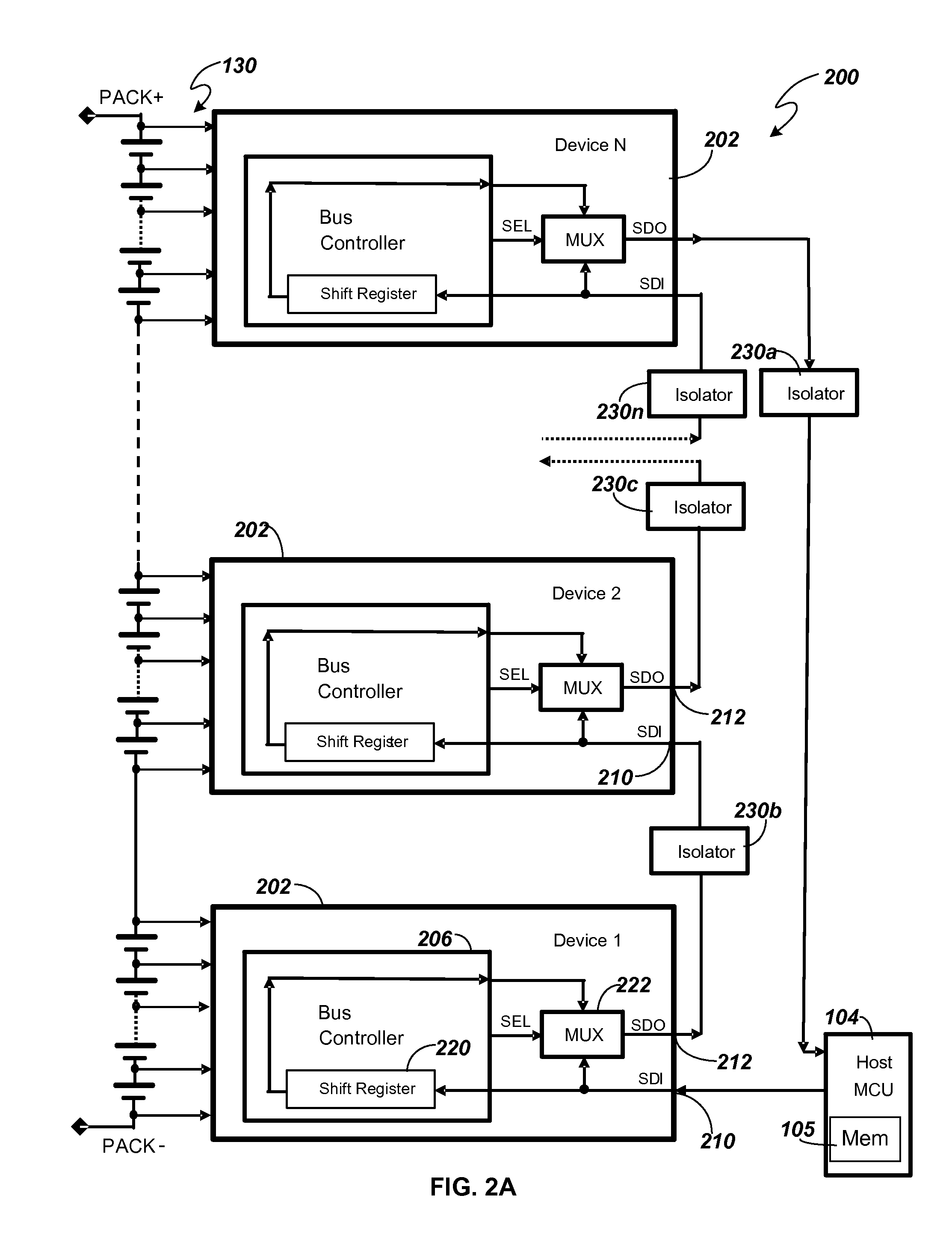
[0013]A system, apparatus and / or method consistent with the present disclosure are configured to assign addresses to a plurality of devices coupled together in a system. The plurality of devices include at least one serial input port and at least one serial output port. The devices are configured to receive serial data from another device and / or a host controller and to provide serial data to another device and / or host controller via the serial ports. The address(es) may be assigned serially, as described herein. For example, the system may be a battery management system.

[0014]FIG. 1 depicts a block diagram of one embodiment of vertical bus system circuitry 100 consistent with the present disclosure. The embodiment of system circuitry 100 is configured as a vertical bus with non-common ground as described herein. The vertical bus system 100 may each include a plurality of devices 102. Each device 102 includes device circuitry. For example, the vertical bus system 100 may include a p...


PUM


Abstract

According to one aspect there is disclosed an apparatus. The apparatus may include a first device. The first device may include a first serial input port configured to receive serial data from at least one of a host MCU and a second device; a first serial output port configured to output the serial data to a third device when the third device is coupled to the first device; a first shift register configured to receive the serial data from the first serial input port; a first multiplexer configured to selectively couple the first serial output port to the first shift register or the first serial input port; and a bus controller configured to receive the serial data from the first serial input port, the bus controller further configured to control the first multiplexer to couple the first serial output port to the first serial input port or the first shift register, based at least in part on the serial data, wherein the serial data includes a command section of a command and at least a portion of a payload section of the command, wherein the command section includes a command code, a target address and an error check and the payload section includes at least one new address and at least one corresponding error check.

Description

BACKGROUND[0001]A plurality of devices may be coupled together. In order to individually access each of the plurality of devices, each device should have a unique identifier, i.e., address. It may be desirable for each device to be manufactured identically to each other device, providing savings in both manufacturing cost and the time to manufacture the devices. In operation, however, it may be desirable to individually address each device, e.g., in order to access a particular device. It may also be desirable to assemble the plurality of devices into a system without consideration of a relative position of each device in the system. Providing unique addresses at manufacturing can be done but adds time and cost to the manufacturing process. It may therefore be desirable to identify and assign unique addresses to the devices after they have been assembled into the system.SUMMARY[0002]According to one aspect there is disclosed an apparatus. The apparatus may include a first device. Th...

Claims


Application Information

Patent Timeline
IPC IPC(8): G06F3/00G06F13/00
CPCG06F13/4282
Inventor ZENG, XIAOJUNSHENG, KAIYA
Owner O2 MICRO INT LTD
Learn More