Adjustable air handler stand and filter rack

a filter rack and air handler technology, applied in the direction of dismountable cabinets, lighting and heating apparatus, heating types, etc., can solve the problem of not providing the additional features required of air handlers

Active Publication Date: 2013-01-08
JANLERT PEREZ
View PDF16 Cites 39 Cited by
  • Summary
  • Abstract
  • Description
  • Claims
  • Application Information

AI Technical Summary

Benefits of technology

[0010]It is an object of the present invention to provide base assembly for air handlers having a filter that is sturdy and capable to support heavy air handlers.
[0012]Another object of this invention is to provide a filter track that facilitates the replacement of filters when the track is not a built-in feature of the air handler.
[0013]It is yet another object of this invention to provide such a device that is inexpensive to manufacture and maintain while retaining its effectiveness.

Problems solved by technology

However, it differs from the present invention because it does not provide additional features required by an air handler, i.e. double adjustable screw both for the height and for the lateral size.

Method used


Image

  • Adjustable air handler stand and filter rack
  • Adjustable air handler stand and filter rack
  • Adjustable air handler stand and filter rack

Examples


Embodiment Construction

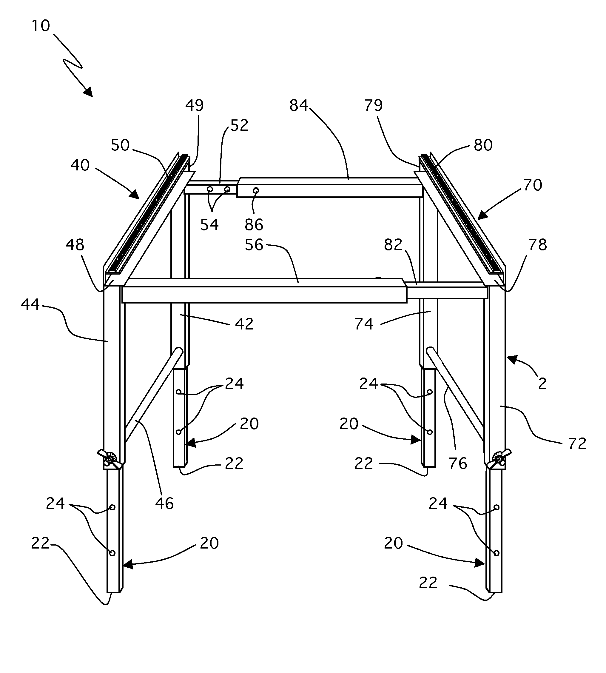
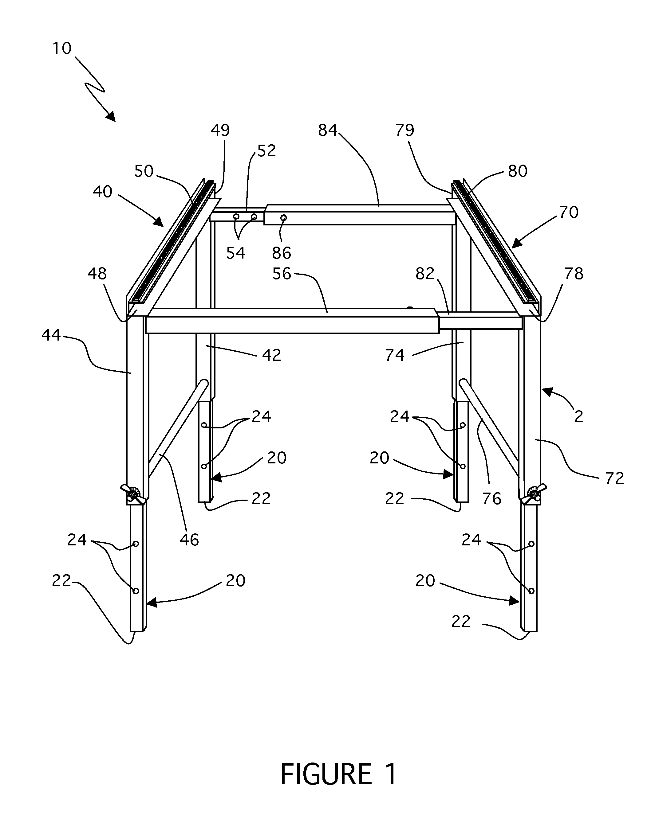
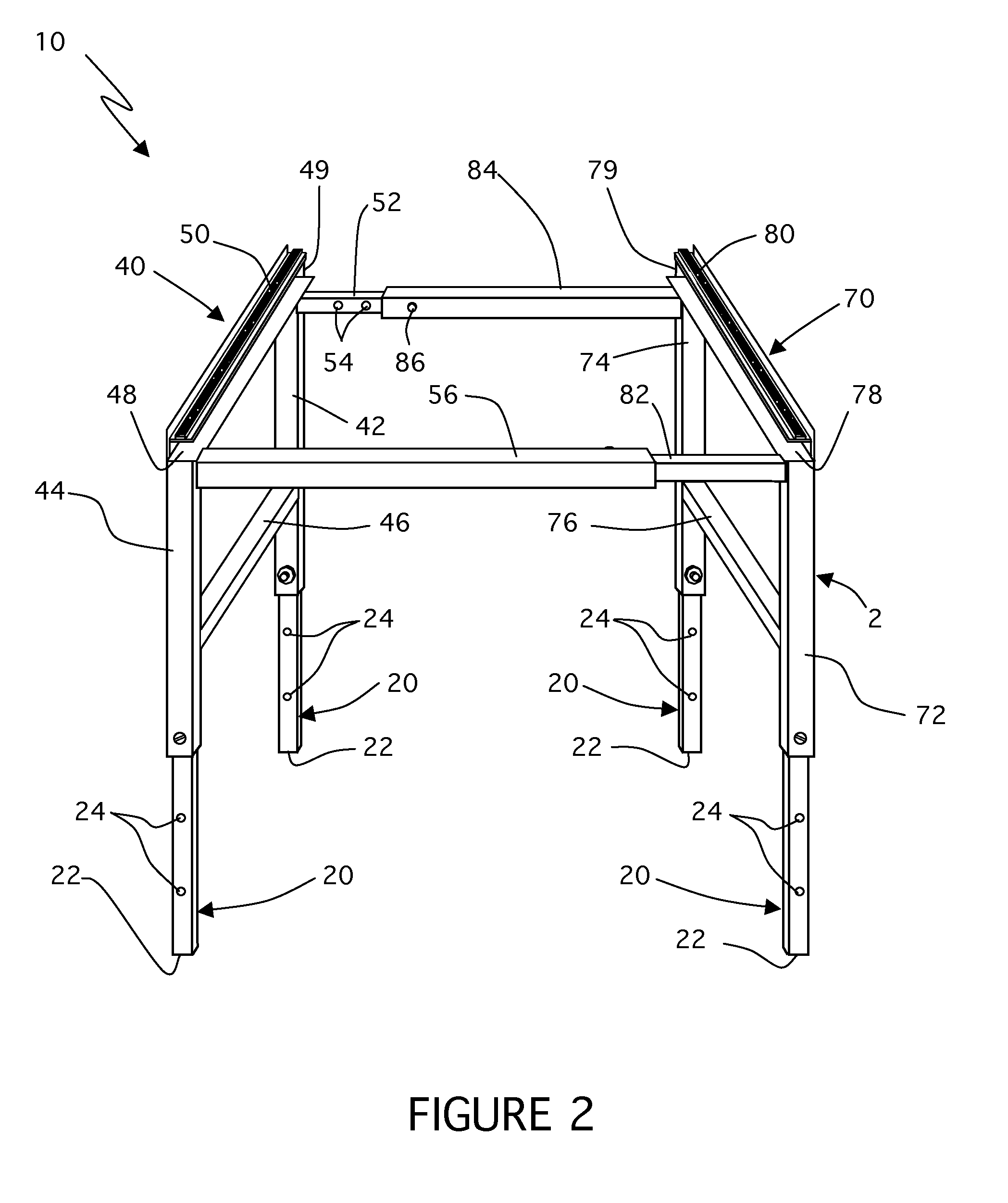
[0018]Present invention 10 is a base assembly for air handlers having a filter. It basically comprises metallic legs 20, first metallic upper frame 40, and second metallic upper frame 70.

[0019]As seen in FIGS. 1 and 2, metallic legs 20 each have distal end 22. Each metallic legs 20 also has first through holes 24 at first predetermined distances from each distal end 22. Metallic legs 20 having a rectangular or square cross section, and each distal end 22 mounts to a floor.

[0020]First metallic upper frame 40 comprises first and second vertical extensions 42 and 44 to telescopically receive a first set of metallic legs 20 respectively. First metallic upper frame 40 further comprises first brace member 46 extending between first and second vertical extensions 42 and 44. First metallic upper frame 40 further comprises first air filter C-shaped track 48 extending between first and second vertical extensions 42 and 44. Stopper 49 is at one end of air filter C-shaped track 48. First air fi...


PUM


Abstract

A base assembly for air handlers having a filter. Four metallic legs each have a distal end. The metallic legs also have first through holes at first predetermined distances from their respective distal ends. The metallic legs have a rectangular or square cross section, and each distal end mounts to a floor. First and second metallic upper frames have vertical extensions to telescopically receive the four metallic legs respectively. The first and second metallic upper frames further have braces member and air filter C-shaped tracks. The first and second metallic upper frames each further have elongated male horizontal arms and elongated female horizontal arms that join whereby the air filter C-shaped tracks face each other to receive a filter.

Description

CROSS REFERENCE TO RELATED APPLICATIONS[0001]This application claims priority to provisional U.S. patent application Ser. No. 60 / 947,650 filed Jul. 2, 2007.STATEMENT REGARDING FEDERALLY RELATED RESEARCH OR DEVELOPMENT[0002]Applicant states that no federal funding was involved directly or indirectly in the research and development of the object of the present invention.BACKGROUND OF THE INVENTION[0003]1. Field of the Invention[0004]The present invention relates to air conditioning equipment, and more specifically, to base assemblies for air handlers having a filter.[0005]2. Description of the Related Art[0006]Applicant believes that the closest reference corresponds to Gonzalez U.S. Pat. No. 5,407,171 and entitled “Adjustable Air Handler Base Assembly”. However, it differs from the present invention because it does not provide additional features required by an air handler, i.e. double adjustable screw both for the height and for the lateral size.[0007]The invention disclosed in the ...

Claims


Application Information

Patent Timeline
Patent Type & Authority Patents(United States)
IPC IPC(8): A47F5/00A47B43/00F16M11/00
CPCF16M5/00F16M11/32F24F13/32
Inventor JANLERT, PEREZ
Owner JANLERT PEREZ
Why Eureka
Try Eureka