
Timepiece

a timepiece and timepiece technology, applied in the field of timepieces, can solve the problems of damage to or poor durability of metal bearings, and long time-consuming use, and achieve the effect of preventing damage to and deformation of timepiece parts

Inactive Publication Date: 2013-01-08
SEIKO EPSON CORP
View PDF11 Cites 12 Cited by
  • Summary
  • Abstract
  • Description
  • Claims
  • Application Information

AI Technical Summary

Benefits of technology

The present invention is a timepiece that can prevent damage and deformation of its parts.

Problems solved by technology

The impact stress produced by the collision between the striking member and the struck member can result in damage to or deformation of timepiece parts including the striking member and the struck member.
Considering in particular the bearing, that is, the struck member, if the bearing is made from a material with high hardness such as ruby, fractures may occur during use for a long period of time as a result of repeated impact between the staff and the bearing.
Such fractures can be avoided by using a metal bearing, but the durability of metal bearings is poor, and wear from rotation of the staff and impact during the flyback operation can eventually deform the bearing.
Yet, further, common metals that can improve resistance to wear and deformation are difficult to process and are not suited to mass production of timepieces.

Method used


Image

  • Timepiece
  • Timepiece
  • Timepiece

Examples


Embodiment Construction

[0029]A preferred embodiment of the present invention is described below with reference to the accompanying figures.

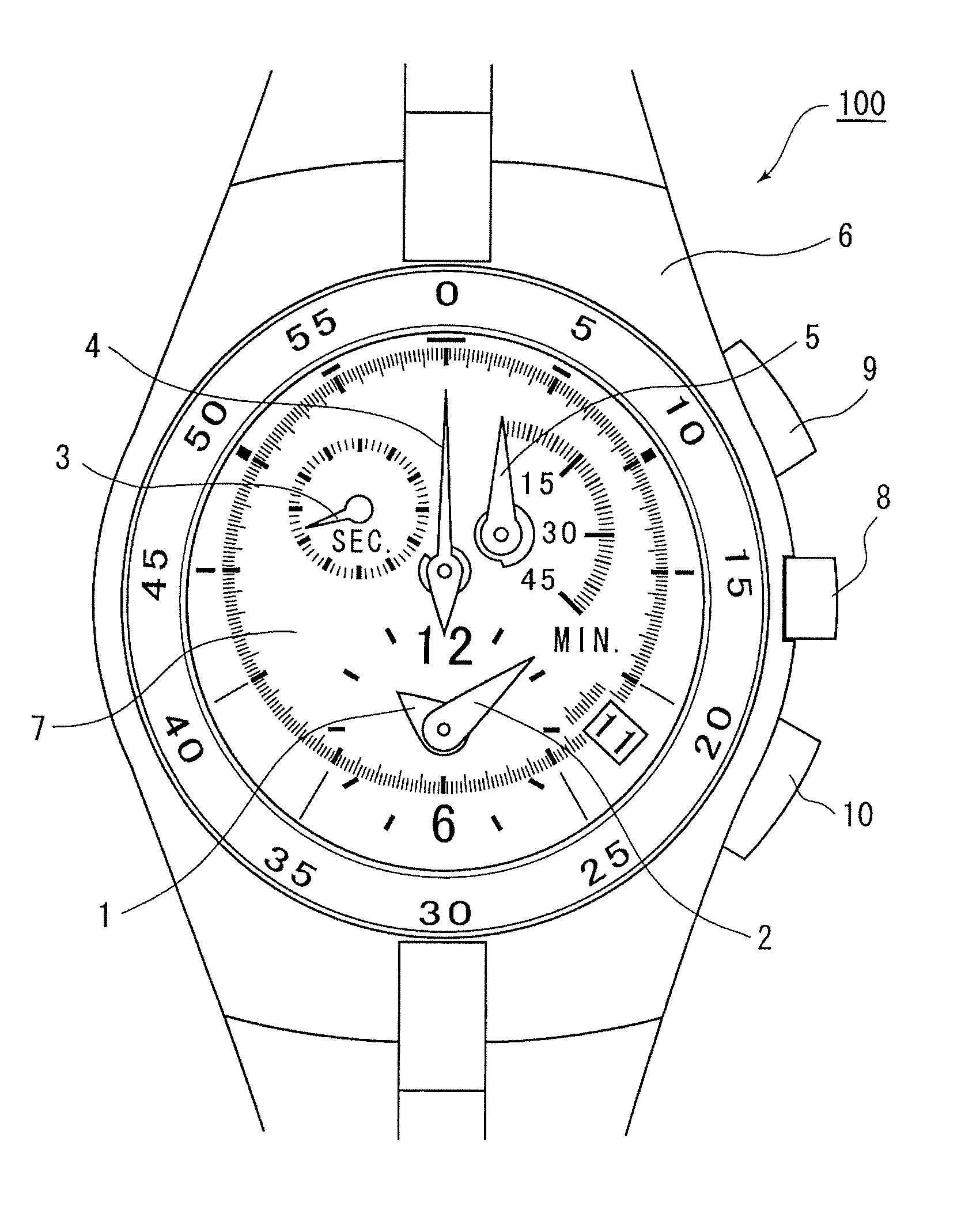
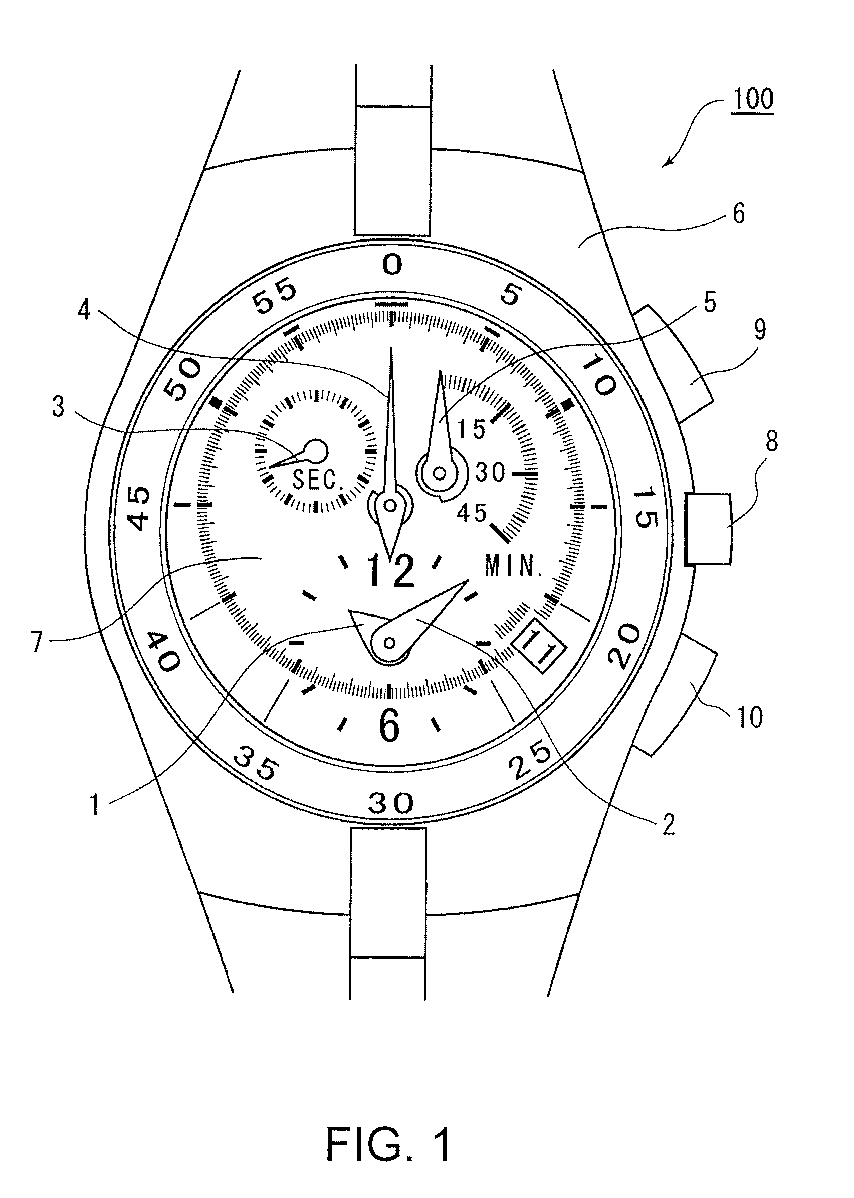
[0030]FIG. 1 is a top plan view of a timepiece according to a preferred embodiment of the invention.

[0031]Referring to FIG. 1, a chronograph timepiece described below as a preferred embodiment of a timepiece according to the invention has an hour hand 1 and a minute hand 2 disposed coaxially to display the time in a common analog manner offset towards 6:00 o'clock from the center of the case 6 of the timepiece 100, and has a small seconds hand 3 for displaying the second of the normal time in a subsidiary dial at 10:00 o'clock.

[0032]A chronograph seconds hand 4 (a “chronograph hand” in the accompanying claims) for indicating the chronograph seconds is offset slightly eccentrically towards 12:00 o'clock from the center of the case 6 of the timepiece 100. A chronograph minute hand 5 (a “chronograph hand” in the accompanying claims) for indicating the chronograph minute m...


PUM


Abstract

A timepiece includes a striking member and a struck member that is driven when struck by the striking member, at least one of the striking member and the struck member being made from a metallic glass alloy.

Description

BACKGROUND[0001]1. Technical Field[0002]The present invention relates to a timepiece having a configuration in which a striking member strikes a struck member.[0003]2. Related Art[0004]Chronograph timepieces having an analog display using hands to indicate normal time also have chronograph hands such as a seconds chronograph hand and a minute chronograph hand to indicate chronograph time. The chronograph hands are made to start and stop keeping chronograph time, and are reset to zero, when operating buttons disposed to the timepiece are operated appropriately. The operation that returns the chronograph hand from where it stops to the original zero position (“return-to-zero” operation) is accomplished by pressing a flyback lever against a heart-shaped cam (heart cam) affixed to the staff on which the chronograph hand is disposed. See, for example, International Patent Application No. WO / 1999 / 054792 and Japan Registered Utility Model U2605696.[0005]In a chronograph timepiece such as d...

Claims


Application Information

Patent Timeline
Patent Type & Authority Patents(United States)
IPC IPC(8): G04F7/00G04F8/00G04B29/00
CPCG04B13/026G04B31/004G04F7/08G04B13/023G04F7/0814
Inventor KAMIYA, HIDEKI
Owner SEIKO EPSON CORP
Learn More