Operating lever structure for vehicle seat, and method of manufacturing operating lever structure

a technology of operating lever and vehicle seat, which is applied in the direction of chairs, furniture parts, manufacturing tools, etc., can solve the problems of inconvenient workability, complicated installation work, and difficulty in ensuring the space of the lifting lever, and achieve the effect of improving workability

Active Publication Date: 2013-01-15
TOYOTA BOSHOKU KK
View PDF24 Cites 32 Cited by
  • Summary
  • Abstract
  • Description
  • Claims
  • Application Information

AI Technical Summary

Benefits of technology

[0008]The invention ensures space for arranging a lifter lever (seat cushion lifting and lowering lever) for carrying out lifting and lowering operation of a lifting and lowering mechanism, which changes the vertical position of a seat cushion, in an operating lever structure for a vehicle seat in which an opening through which a seat belt extends is provided adjacent to the lifting and lowering mechanism and a fixed end portion of the seat belt is connected to a frame of the seat cushion. In addition, the invention improves workability for installing an outer shield (shielder).
[0013]Thus, when the lifting and lowering lever and the reclining lever are operably exposed outside while the shielder is installed to the side portion of the seat cushion, the installation worker is not required to check whether both the lifting and lowering lever and the reclining lever protrude from the shielder at the same time. This can reduce the workload of the installation worker. Thus, it is possible to improve workability for installing the shielder.

Problems solved by technology

If the lifting and lowering mechanism for lifting and lowering the seat cushion is installed onto the frame to which the fixed end portion of the seat belt is connected, there is a problem that it is difficult to ensure space for arranging the lifter lever because the opening through which the seat belt extends and the lifting and lowering mechanism are located adjacent to each other.
As a result, installation work becomes complicated, and it is inconvenient in terms of workability.

Method used


Image

  • Operating lever structure for vehicle seat, and method of manufacturing operating lever structure
  • Operating lever structure for vehicle seat, and method of manufacturing operating lever structure
  • Operating lever structure for vehicle seat, and method of manufacturing operating lever structure

Examples


Embodiment Construction

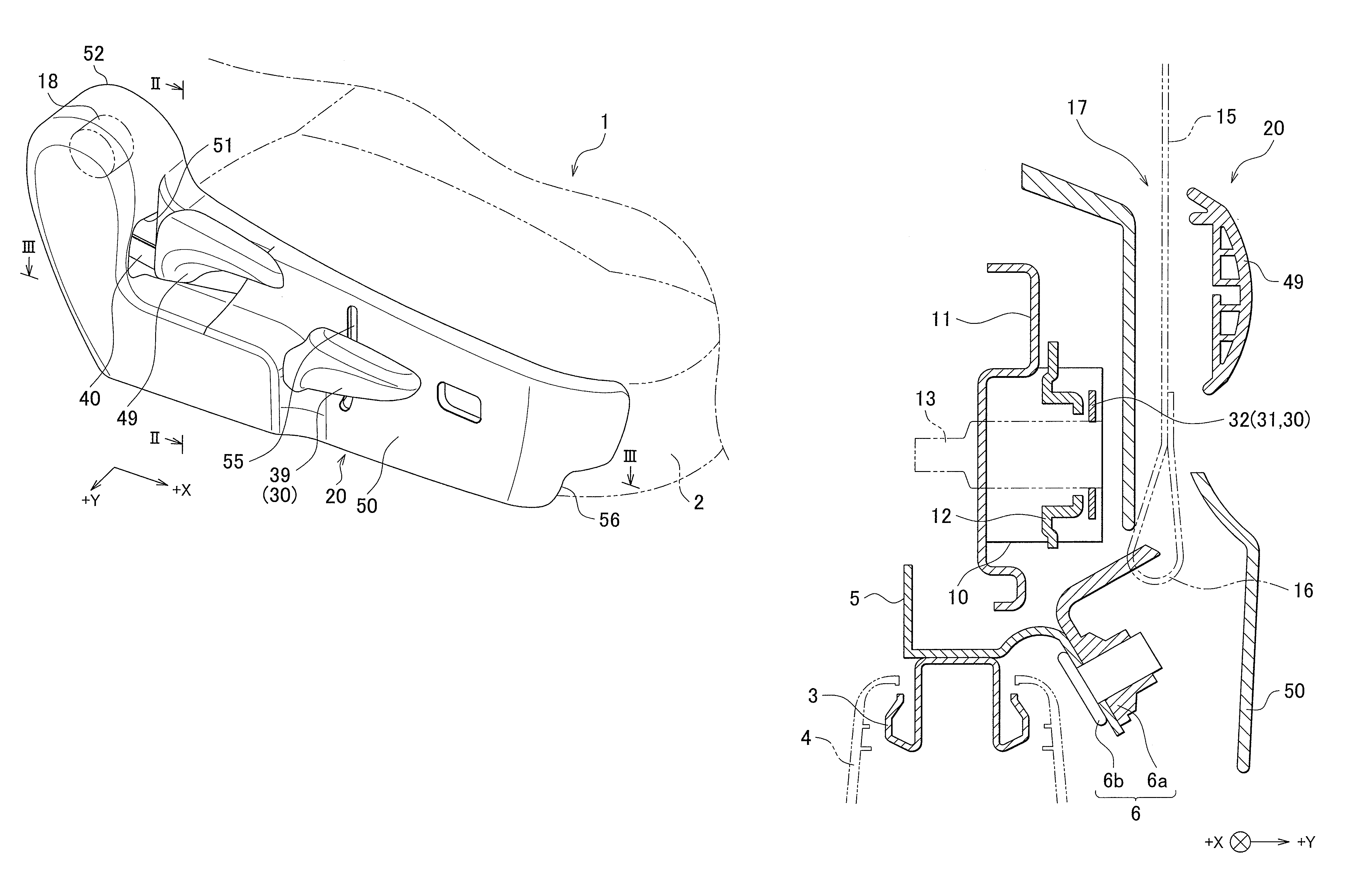
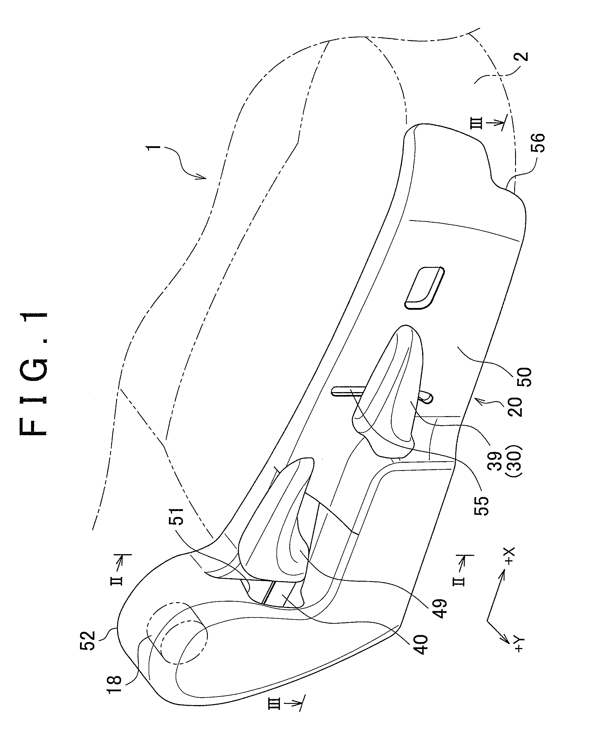
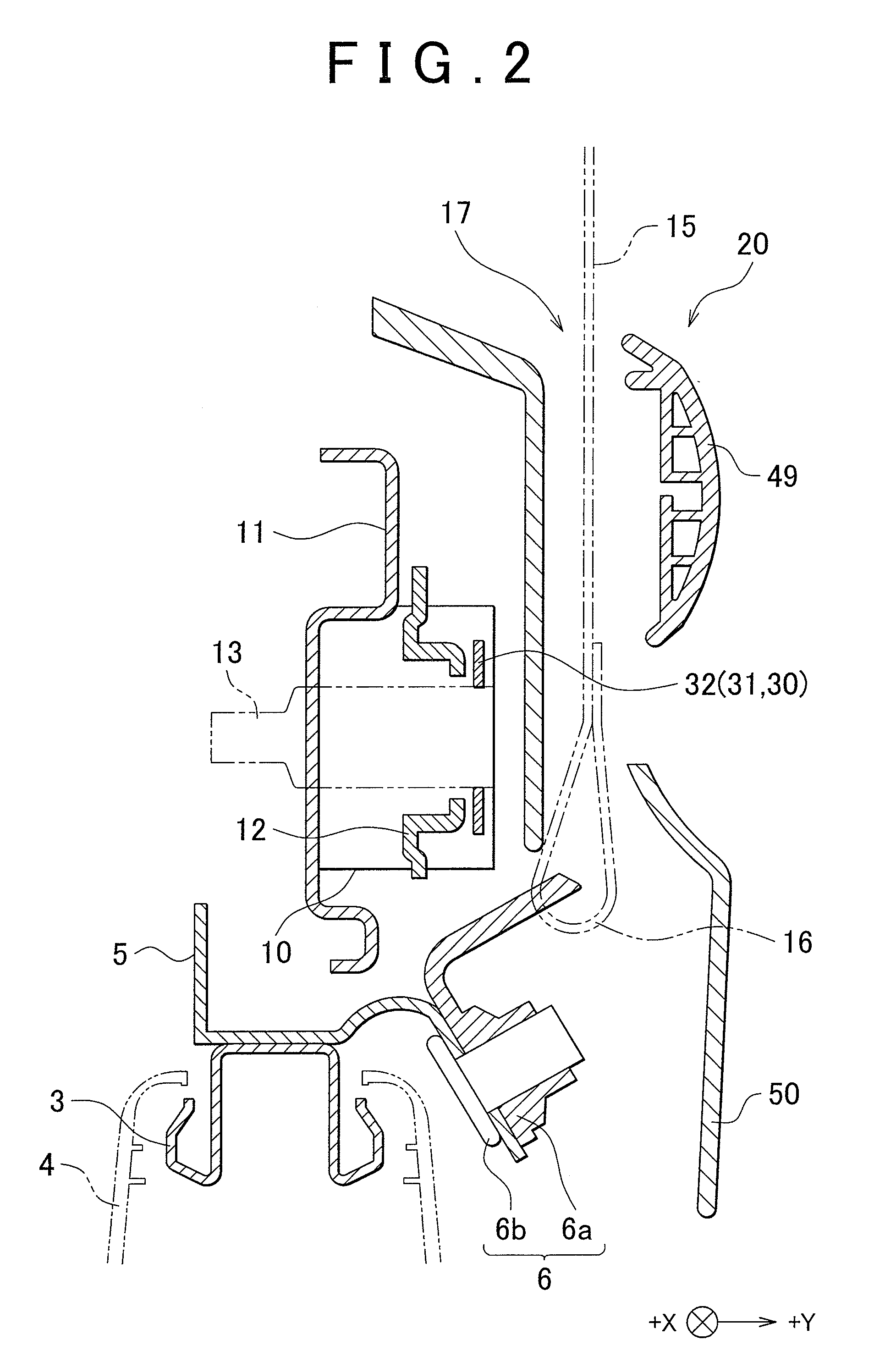
[0020]Hereinafter, an embodiment of the invention will be described with reference to the accompanying drawings. FIG. 1 is a perspective view that shows an operating lever structure 20 for a vehicle seat 1, which is installed at a side portion of a seat cushion, according to the embodiment. FIG. 2 is a cross-sectional view of the operating lever structure 20 for the vehicle seat 1, taken along the line II-II in FIG. 1. FIG. 3 is a cross-sectional view of the operating lever structure for the vehicle seat, taken along the line III-III in FIG. 1. The vehicle seat 1 is installed in a vehicle, such as an automobile, and, although not specifically shown in the drawings, the vehicle seat 1 includes a seat cushion 2, a seat back, a head rest, an arm rest, and the like. The vehicle seat 1 is able to change the position of the seat cushion 2 and the position of the seat back. That is, as shown in FIG. 2 and FIG. 3, the seat cushion 2 includes a lifting and lowering mechanism 10 that lifts or...


PUM

PropertyMeasurementUnit
widthaaaaaaaaaa
lengthaaaaaaaaaa
workabilityaaaaaaaaaa

Abstract

In an operating lever structure for a vehicle seat in which an opening through which a seat belt extends is provided adjacent to a seat cushion lifting and lowering mechanism and a fixed end portion of the seat belt is connected to a seat cushion frame, a lifter lever includes a plate-like extending portion that is coupled to the lifting and lowering mechanism and a protrusion portion. The plate-like extending portion extends toward a front of the seat. The protrusion portion extends from the front end of the plate-like extending portion toward the outside in the seat width direction. The protrusion portion protrudes from an outer shield through a first exposing port of the outer shield, installed to a side portion of the seat cushion.

Description

INCORPORATION BY REFERENCE[0001]The disclosure of Japanese Patent Application No. 2008-264049 filed on Oct. 10, 2008 including the specification, drawings and abstract is incorporated herein by reference in its entirety.BACKGROUND OF THE INVENTION[0002]1. Field of the Invention[0003]The invention relates to an operating lever structure for a vehicle seat installed in a vehicle, the operating lever structure being operated by an occupant when the position of a seat cushion or the position of a seat back is changed. More specifically, the invention relates to an operating lever structure for a vehicle seat, in which an opening through which a seat belt extends is provided adjacent to a lifting and lowering mechanism that changes the vertical position of the seat cushion, and a fixed end portion of the seat belt is connected to a frame of the seat cushion.[0004]2. Description of the Related Art[0005]A vehicle seat installed in a vehicle includes components, such as a seat cushion and a...

Claims


Application Information

Patent Timeline
Patent Type & Authority Patents(United States)
IPC IPC(8): A47C7/02B60N2/90
CPCB60N2/44B60N2/6009B60R22/34Y10T29/49826B60R2022/1818B60N2/90
Inventor YAMAZAKI, AKIRATOMONARI, YOSHITAKA
Owner TOYOTA BOSHOKU KK
Why Eureka
Try Eureka