
Lens arrangement for optical rotary joints

a technology of optical rotary joints and lenses, applied in the field of optical rotary joints and lens systems, can solve problems such as unexpected early failures, and achieve the effect of preventing bonding and increasing reliability

Active Publication Date: 2013-01-15
SCHLEIFRING & APPBAU
View PDF14 Cites 7 Cited by
  • Summary
  • Abstract
  • Description
  • Claims
  • Application Information

AI Technical Summary

Benefits of technology

[0011]An object of the disclosure set forth herein is to provide a low-cost optical rotary joint, and also a lens system for a rotary joint of this kind, wherein the lens system can be manufactured reproducibly and exhibits only an extremely small number of early failures, and thus an increased reliability. Furthermore, a method is provided herein for manufacturing a lens system of this kind.
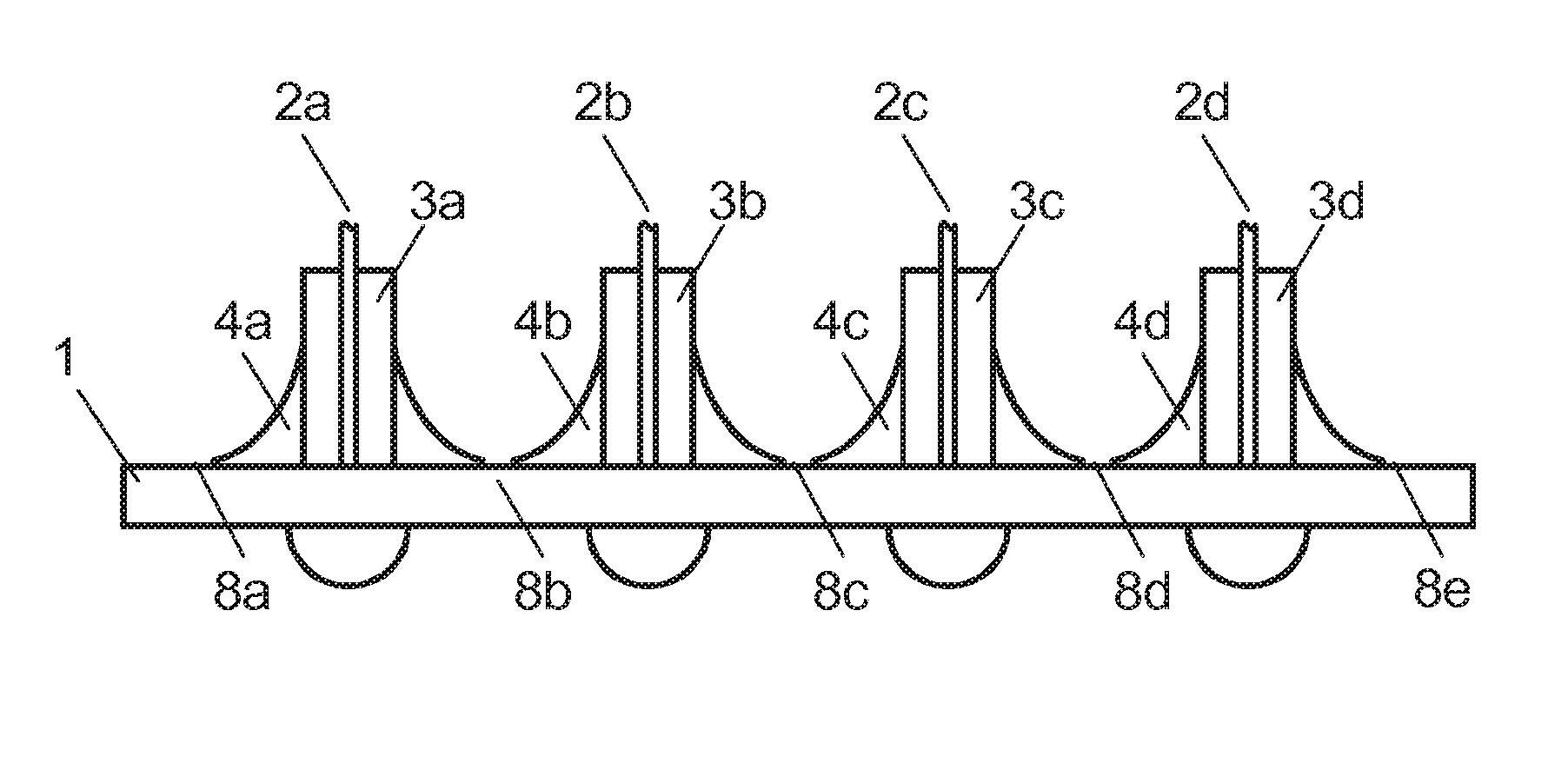
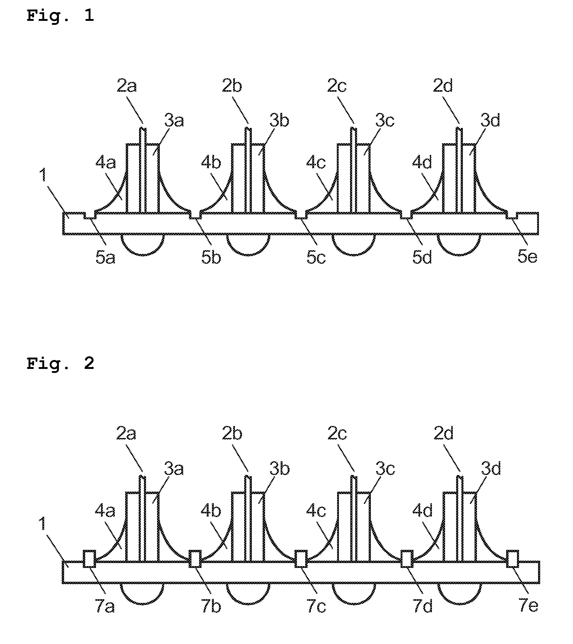
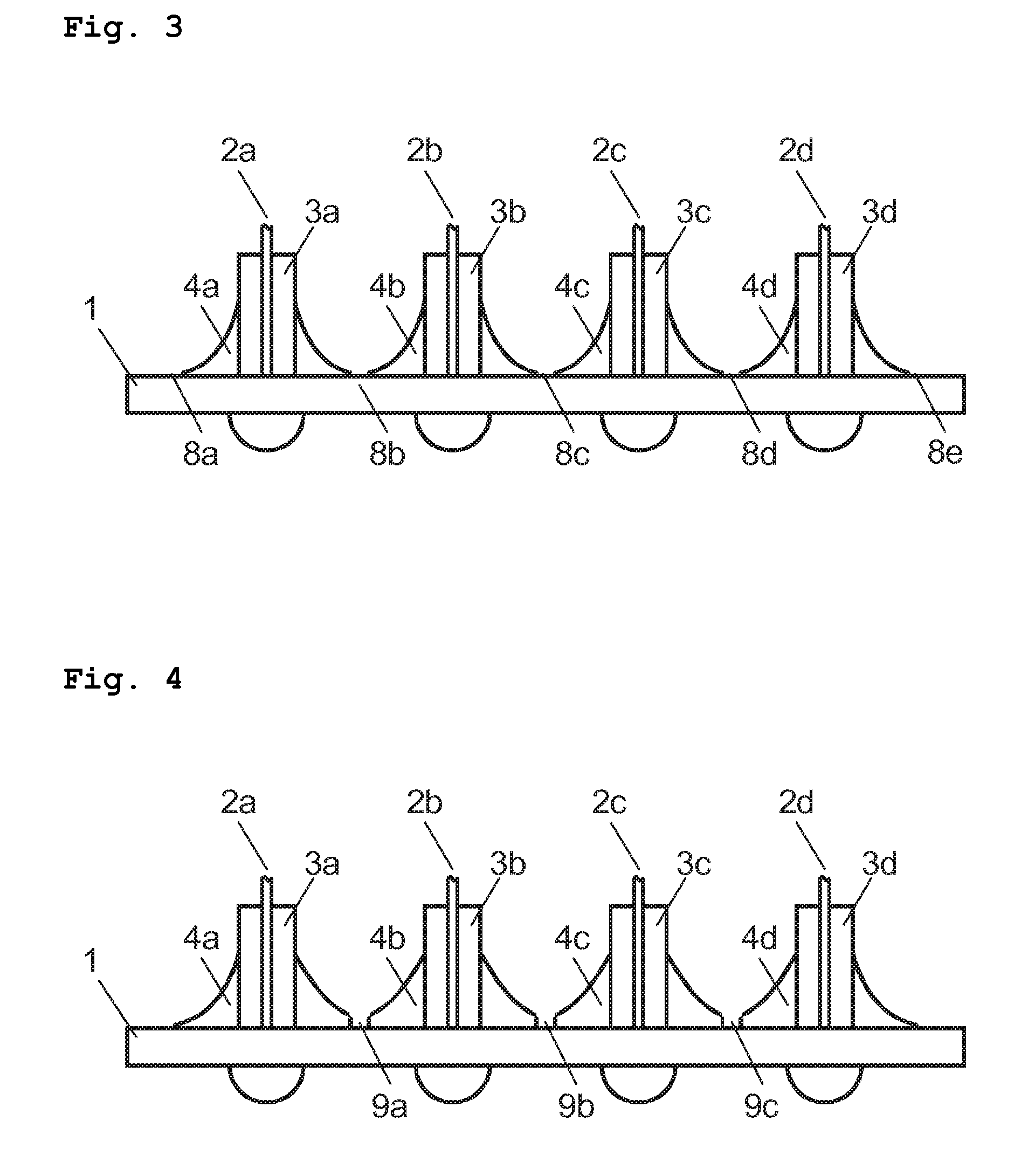
[0012]According to one embodiment, a lens systems comprises a micro-lens array and either: (i) a plurality of ferrules enclosing end-portions of light waveguides, or (ii) a plurality of light waveguides without ferrules, wherein the ferrules or light waveguides are adhesively fastened in a spaced relationship from each other to one side surface of the micro-lens array by means of an adhesive. In one embodiment, bonding between the adhesive applied to neighboring ferrules or light-waveguides is prevented by providing at least one of trenches, barriers, and coatings between the ferrules or the light waveguides on the one side surface of the micro-lens array on which the ferrules or light-waveguides are fastened. In an alternative embodiment, adhesive which has been applied to neighboring ferrules or light wave-guides to form adhesive joints between the ferrules or light-waveguides and the surface of the micro-lens array, and which has run together to form overlapping neighboring adhesive joints, is removed from between the ferrules or light-waveguides to prevent bonding between the neighboring adhesive joints.

Problems solved by technology

In particular, with collimators having a large number of lenses, unexpected early failures occur after only a short period of operation.

Method used


Image

  • Lens arrangement for optical rotary joints
  • Lens arrangement for optical rotary joints
  • Lens arrangement for optical rotary joints

Examples


first embodiment

[0047]FIG. 13 shows an optical arrangement having bores 22, 23 for supplying UV light to an adhesive joint 4. A first part 20 (first optical component) is fixed to a second part 21 (second optical component) by means of an adhesive 4. In this example, the first part 20 and the second part 21 are not transparent to light, and in some cases, may exhibit high attenuation of UV light. One of the parts 20, 21 can be, for example, a ferrule or another fiber holder comprised of a material such as a metal or a ceramic. Curing of the adhesive 4 by lateral light irradiation between the first part 20 and the second part 21 is hardly possible, because light must be introduced into a relatively narrow gap (i.e., the gap between the first part 20 and the second part 21) to the far inside of the adhesive, and only small radiation intensities can be achieved in the inside because of light absorption by the adhesive.

[0048]Therefore, light-guiding channels such as, for example, the first bore 22 and ...

second embodiment

[0049]FIG. 14 shows an optical arrangement, similar to that shown in FIG. 13, but with a transparent intermediate substrate 24. A transparent intermediate substrate 24, which has a boundary face adjacent to the adhesive 4, is provided between the first part 20 and the second part 21. The transparent intermediate substrate 24 preferably has a low transit attenuation for UV light and is preferably designed so that it achieves a uniform light deflection of outside light coupled laterally into the adhesive 4.

third embodiment

[0050]FIG. 15 shows an optical arrangement with a transparent intermediate substrate 24. In FIG. 15, UV radiation 27 is coupled into the intermediate substrate 24 laterally from an external light source (not shown) by means of a light guide 28. The light conducted in the intermediate substrate 24 is then deflected into the adhesive 4, as illustrated by arrows.


PUM


Abstract

According to one embodiment, an optical rotary joint comprises a first collimator arrangement for coupling-on first light-waveguides, and a second collimator arrangement for coupling-on second light-waveguides, with the latter being rotatably supported relative to the first collimator arrangement about a rotation axis. A Dove prism is provided between the first and second collimator arrangements as a derotating element. The first and second collimator arrangements have at least one micro-lens array on which light-waveguides with associated ferrules are disposed. In order to avoid tensile forces from arising in the arrangement, or as a result of individual ferrules becoming interconnected by an applied adhesive, trenches, barriers, or also coatings are provided between the individual ferrules.

Description

PRIORITY CLAIM[0001]The present application claims priority to German Patent Application No. 102008001653.5 filed on May 8, 2008.BACKGROUND OF THE INVENTION[0002]1. Field of the Invention[0003]The invention relates to an optical rotary joint, and a lens system particularly for use in optical rotary joints, and also a method for manufacturing a lens system of this kind.[0004]2. Description of the Related Art[0005]Various transmission systems are known for transmission of optical signals between units that are rotatable relative to each other.[0006]U.S. Pat. No. 5,568,578 discloses an optical rotary joint for a plurality of channels, having a Dove prism. An arrangement having a plurality of GRIN lenses is provided for coupling light into or out of glass fibers.[0007]U.S. Patent Application Publication No. 2005 / 0036735 discloses an optical rotary joint for a plurality of channels, having a Dove prism as a derotating element. Light supplied by light-waveguides is coupled via collimators...

Claims


Application Information

Patent Timeline
Patent Type & Authority Patents(United States)
IPC IPC(8): G02B6/32
CPCG02B6/32G02B6/3604
Inventor POPP, GREGORKRUMME, NILS
Owner SCHLEIFRING & APPBAU
Learn More