Variable camshaft timing device with hydraulic lock in an intermediate position

a timing device and camshaft technology, applied in the direction of valve details, valve arrangements, valve drives, etc., can solve the problems of difficult manufacturing, long spool valve and sleeve, and inapplicability,

Active Publication Date: 2013-01-22
BORGWARNER INC
View PDF16 Cites 58 Cited by
  • Summary
  • Abstract
  • Description
  • Claims
  • Application Information

AI Technical Summary

Problems solved by technology

The two features of a spool controlling the lock pin and a hydraulic detent circuit actuated via a control valve to command the VCT to a position somewhere in the middle of the total phase angle range of authority can be combined on one VCT assembly to be controlled by the spool valve, but it is not practical to do so.
The problem with this approach is that there would be three hydraulic circuits on one spool valve, one to control the VCT, one to control the hydraulic detent circuit that commands the VCT to a known intermediate position and one to control the lock pin.
This makes the spool valve and sleeve very long, making them very difficult to manufacture.
In addition, putting all three hydraulic circuits on the control valve increases the overall package length of the VCT, which is not well received in the tight package requirements of the automotive powertrains.
Finally, putting all three control circuits on one spool valve makes for complex and restrictive flow circuits, thus limiting the performance of each circuit.

Method used


Image

  • Variable camshaft timing device with hydraulic lock in an intermediate position
  • Variable camshaft timing device with hydraulic lock in an intermediate position
  • Variable camshaft timing device with hydraulic lock in an intermediate position

Examples


first embodiment

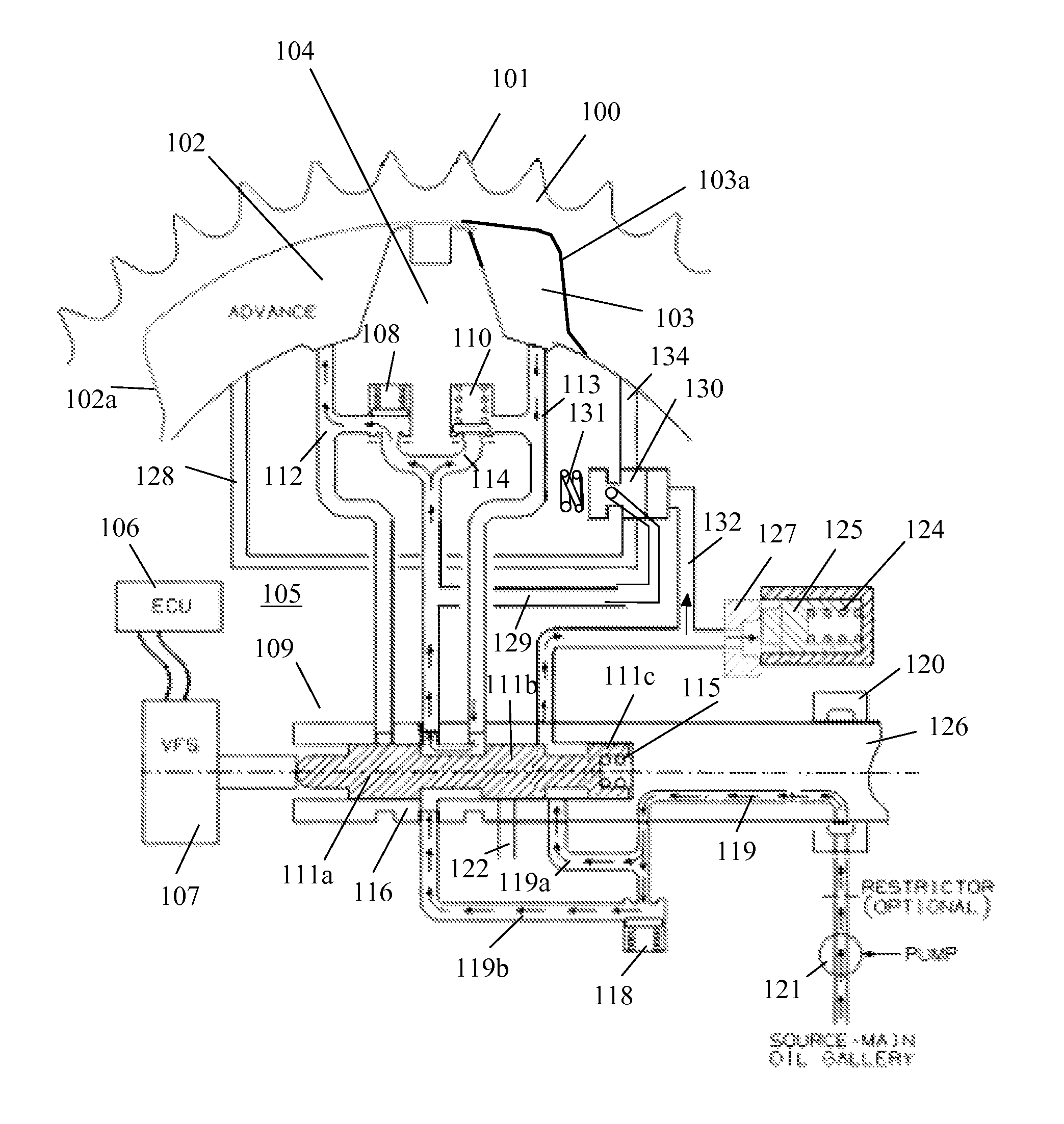
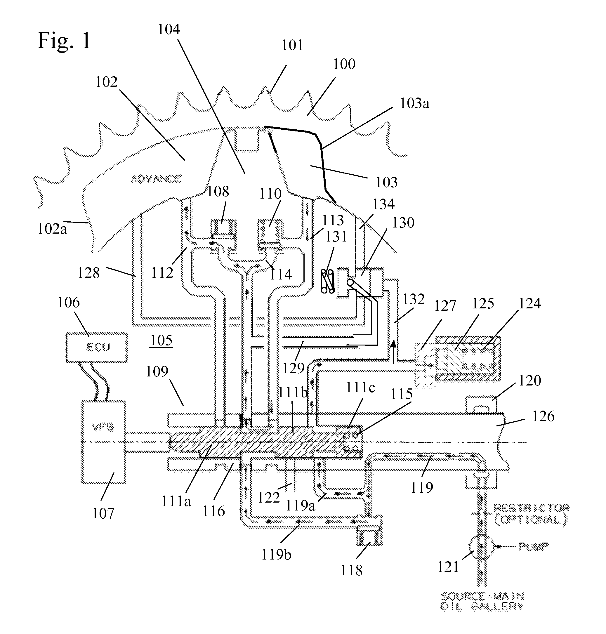
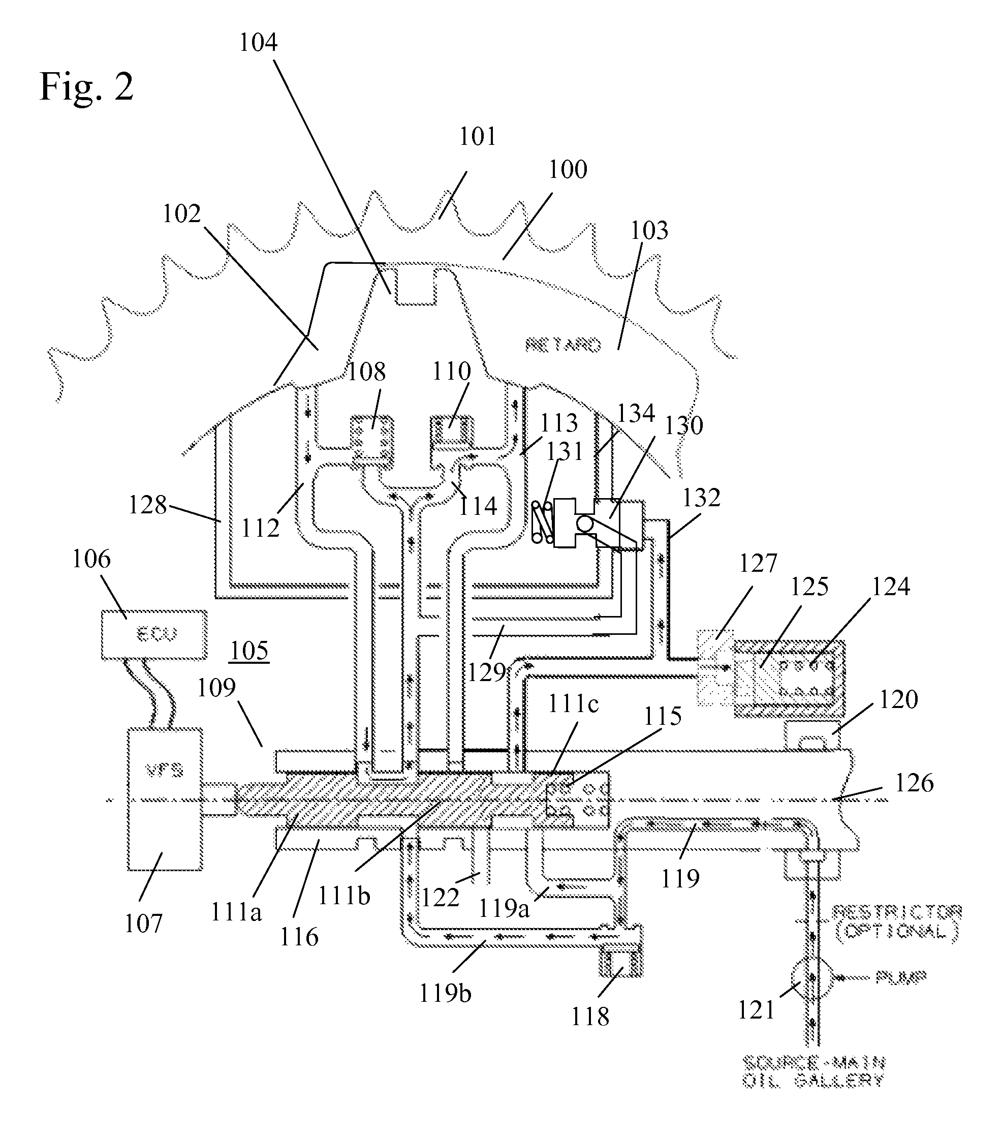
[0044]Referring to FIGS. 1-10 of the first embodiment, torque reversals in the camshaft caused by the forces of opening and closing engine valves move the vane 104, The advance and retard chambers 102, 103 are arranged to resist positive and negative torque pulses in the camshaft 126 and are alternatively pressurized by the cam torque. The control valve 109 allows the vane 104 in the phaser to move by permitting fluid flow from the advance chamber 102 to the retard chamber 103 or vice versa, depending on the desired direction of movement.

[0045]The housing assembly 100 of the phaser has an outer circumference 101 for accepting drive force. The rotor assembly 105 is connected to the camshaft 126 and is coaxially located within the housing assembly 100. The rotor assembly 105 has a vane 104 separating a chamber formed between the housing assembly 100 and the rotor assembly 105 into an advance chamber 102 and a retard chamber 103. The vane 104 is capable of rotation to shift the relativ...

fifth embodiment

[0082]FIGS. 17a-20 show the present invention with the lock pin integrated into the piloted valve to form a piloted lock valve. Movement of the piloted lock valve is actively controlled by the control valve of the phaser. FIG. 17a shows the phaser moving from an advance position towards a mid position or intermediate phase angle position by the open hydraulic detent lock circuit. FIG. 17b shows the phaser moving from a retard position towards a mid position or intermediate phase angle by the open hydraulic detent lock circuit. FIG. 17c shows the phaser just prior to the lock pin end of the piloted lock valve engaging the recess. FIG. 18 shows the phaser in the mid position or intermediate phase angle position with lock pin end of the piloted lock valve engaging the recess. FIG. 19 shows the phaser moving towards the advance position. FIG. 20 shows the phaser moving towards the retard position.

[0083]Torque reversals in the camshaft caused by the forces of opening and closing engine v...


PUM


Abstract

A variable cam timing phaser for an internal combustion engine including a piloted valve in the rotor assembly, movable from a first position to a second position, and detent lines communicating with the advance chamber or the retard chamber are restricted and or blocked when the rotor assembly is in or near an intermediate phase angle position. When the piloted valve is in the first position, fluid is blocked from flowing through the piloted valve. When the piloted valve is in a second position, fluid is allowed to flow between the detent line from the advance chamber and the detent line from the retard chamber through the piloted valve and a common line, such that the rotor assembly is moved to and held in the intermediate phase angle position relative to the housing assembly.

Description

BACKGROUND OF THE INVENTION[0001]1. Field of the Invention[0002]The invention pertains to the field of variable cam timing systems. More particularly, the invention pertains to a variable camshaft timing device with hydraulic lock in an intermediate position.[0003]2. Description of Related Art[0004]U.S. Pat. Nos. 6,814,038 and 6,941,913 disclose a variable cam timing system that utilizes the same spool that controls the VCT system to actively control the lock pin. The positions of the spoors lands directly influence whether source oil is supplied to both the lock pin and either the retard or the advance chamber of the phaser.[0005]U.S. Pat. No. 6,666,181, which is hereby incorporated by reference, discloses a variable cam timing device which can be set to default in an intermediate phase angle position located between the advance and retard mechanical stops. More specifically, a hydraulic detent circuit is actuated via a control valve to command the variable cam timing (VCT) device ...

Claims


Application Information

Patent Timeline
Patent Type & Authority Patents(United States)
IPC IPC(8): F01L1/34
CPCF01L1/3442F01L2001/34433F01L2001/34479F01L2001/34469F01L2001/34453
Inventor SMITH, FRANKLIN R.
Owner BORGWARNER INC
Why Eureka
Try Eureka