
Lever-type connector

a connector and lever technology, applied in the direction of coupling device connection, mechanical control device, instruments, etc., can solve the problems of deteriorating lever operability and lever operability in either direction, and achieve good lever operability

Inactive Publication Date: 2013-01-22
SUMITOMO WIRING SYST LTD
View PDF10 Cites 21 Cited by
  • Summary
  • Abstract
  • Description
  • Claims
  • Application Information

AI Technical Summary

Benefits of technology

This patent describes a mechanism that allows two housing parts to connect and separate in parallel postures without interference. The mechanism includes a cam system with two cam pins and two cam grooves that can be engaged at the same time. The arrangement of the cam pins is symmetrical, ensuring a well-balanced connection. A stopper is also included to stop rotation of the first gear. The technical effects are good lever operability and ease of connection and separation of the housing parts.

Problems solved by technology

Thus, the separation of the first cam pin 5L constantly precedes between the two housings 1F, 1M and the two housings 1F, 1M interfere with each other, thereby deteriorating lever operability.
In short, one of the two cam pins 5L, 5R inevitably interferes with the cam groove, and lever operability is deteriorated in either case.

Method used


Image

  • Lever-type connector
  • Lever-type connector
  • Lever-type connector

Examples


Embodiment Construction

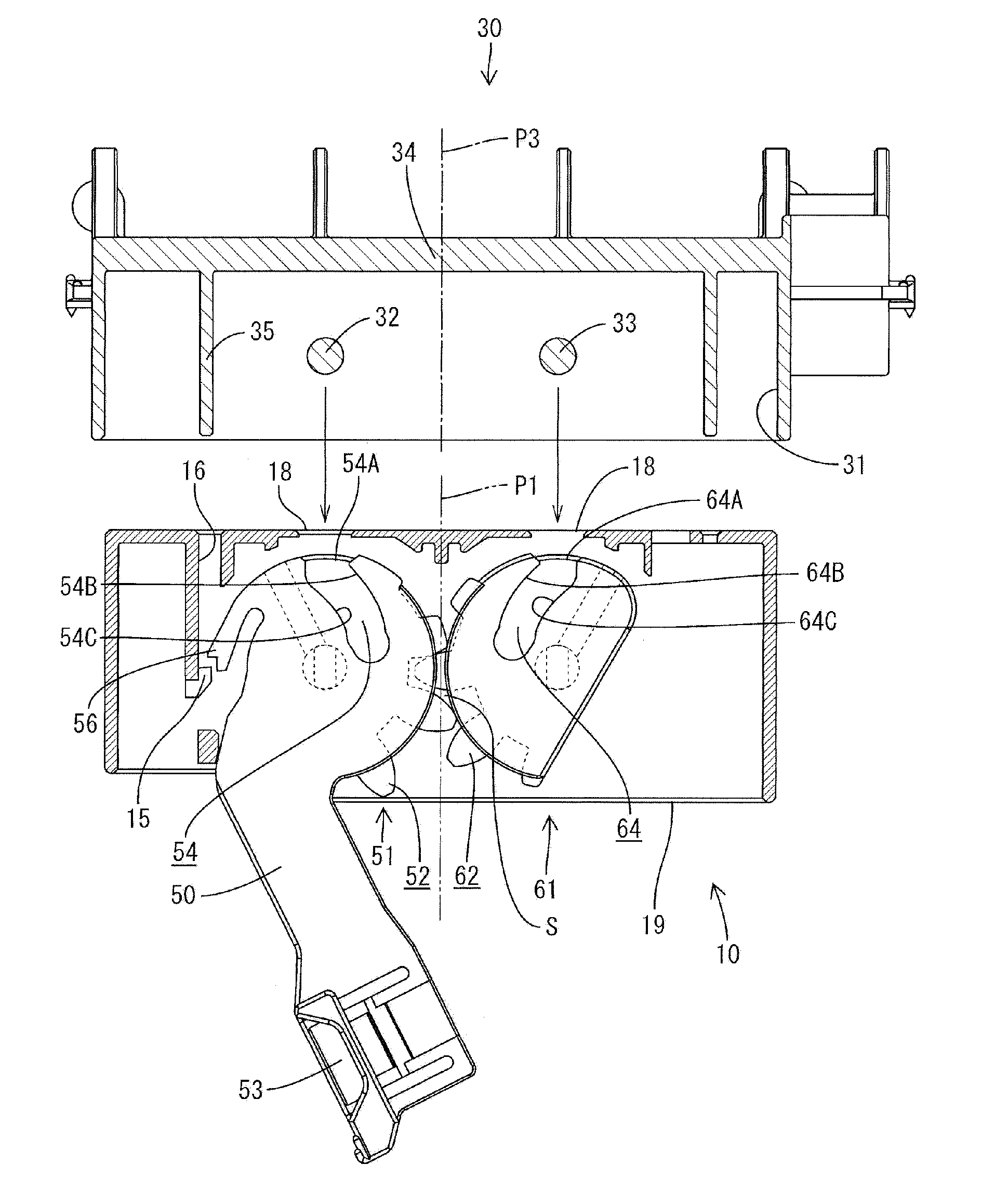
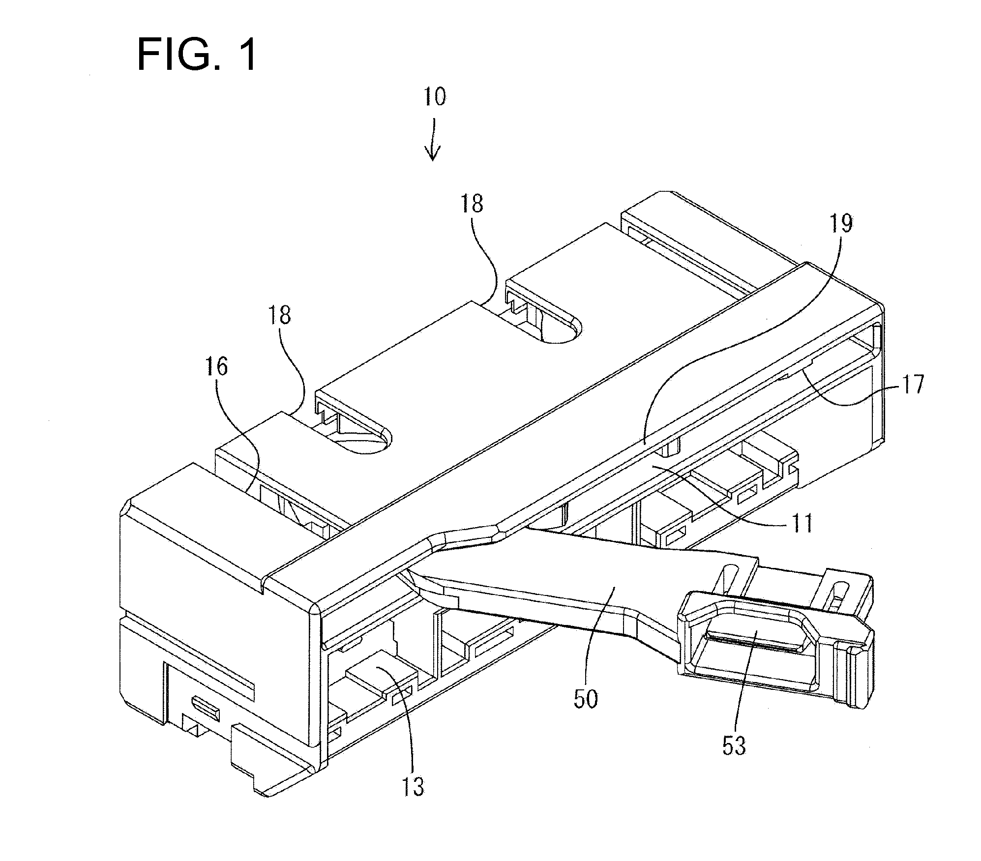
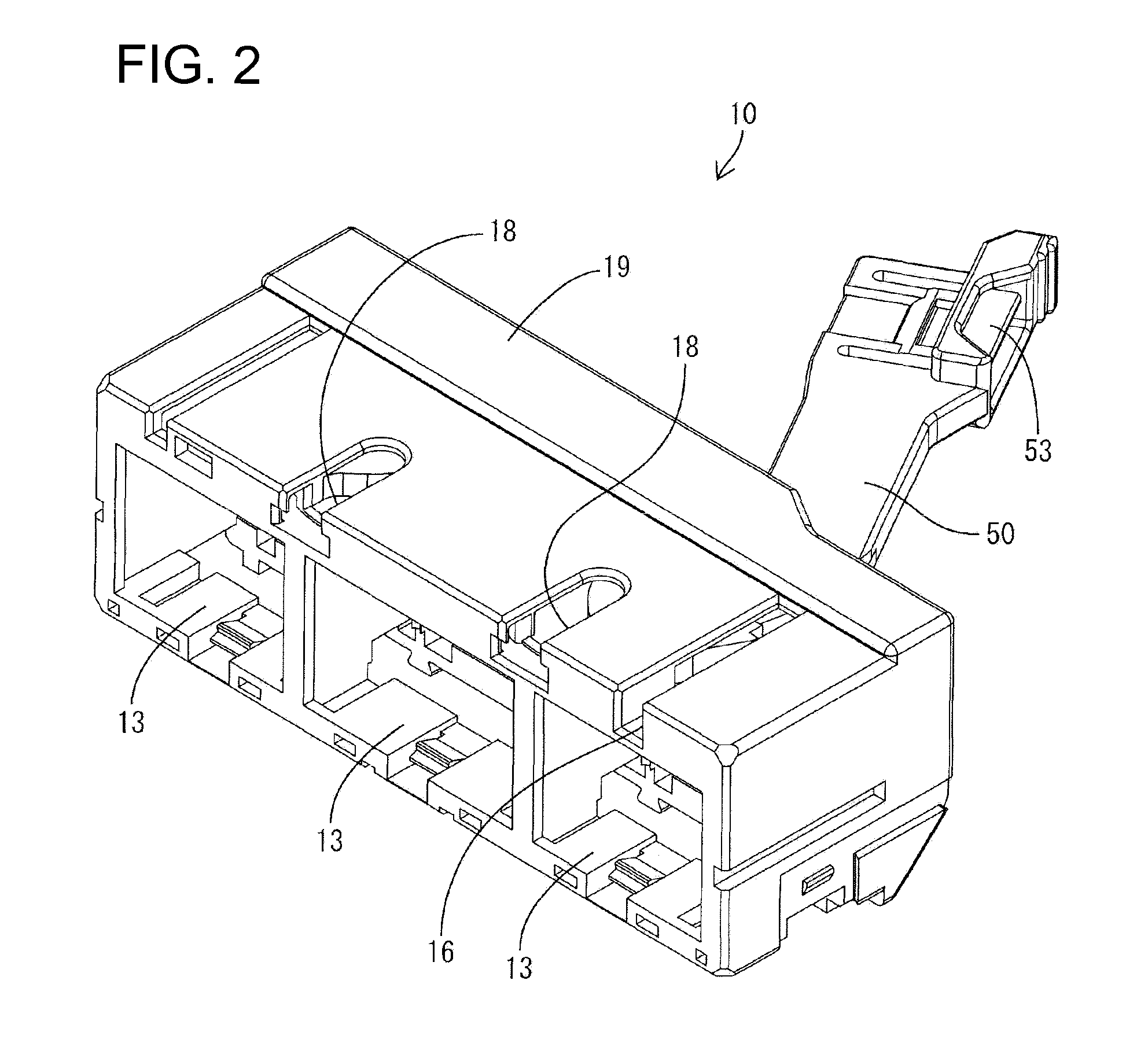
[0039]A lever-type connector in accordance the invention is described with reference to FIGS. 1 to 11. The lever-type connector of this embodiment has a male housing 10, a female housing 30 and a lever 50. The lever 50 is mounted rotatably to the male housing 10, and the male housing 10 can be connected with and / or separated from the female housing 30 as the lever 50 is displaced. In the following description, ends of the two housings 10, 30 to be connected are referred to as front ends concerning forward and backward directions parallel with a connecting direction of the two housings 10, 30.

[0040]The male housing 10 is made e.g. of synthetic resin and the front and rear ends have a wide substantially rectangular shape, as shown in FIGS. 1 and 2. An accommodation space 11 is formed at an upper side of the male housing 10 and opens in the rear surface of the male housing 10 for rotatably accommodating the lever 50. Mounting spaces 13 are arranged in a lower part of the accommodation ...


PUM


Abstract

A lever-type connector has a female housing (30) that can be connected with and separated from a male housing (10) as a lever (50) is rotated. The lever-type connector has first and second cam pins (32, 33). A first gear (51) is rotated as the lever (50) is rotated and has a first cam groove (54) engageable with the first cam pin (32). A second gear (61) is rotated as the first gear (51) is rotated and has a second cam groove (64) engageable with the second cam pin (33). A width of the first cam groove (54) in a direction orthogonal to a moving direction of the first cam pin (32) exceeds the outer diameter of the first cam pin (32) in conformity with a backlash (S) between the two gears (51, 61). A width of the second cam groove (64) in a direction orthogonal to a moving direction of the second cam pin (33) is substantially equal to the outer diameter of the second cam pin (33).

Description

BACKGROUND OF THE INVENTION[0001]1. Field of the Invention[0002]The invention relates to a lever-type connector including two shaft gears.[0003]2. Description of the Related Art[0004]U.S. Pat. No. 5,873,745 and FIGS. 12 to 16 herein show a lever-type connector with a female housing 1F that can be connected with and separated from a male housing 1M as a lever is rotated. FIGS. 12 and 13 show the housings 1F, 1M during a connecting operation, and FIGS. 14 to 16 show the housings 1F, 1M during a separating operation. The connector of FIGS. 12 to 16 also has a lever 4. A first gear 2L is formed integrally on the lever 4 and a second gear 2R is engaged with the first gear 2L. The first gear 2L rotates with the lever 4 and causes the second gear 2R to rotate.[0005]A first cam groove 3L is formed in the first gear 2L and a second cam groove 3R is formed in the second gear 2R. The first and second cam grooves 3L and 3R are arranged symmetrically with respect to a plane of symmetry orthogona...

Claims


Application Information

Patent Timeline
Patent Type & Authority Patents(United States)
IPC IPC(8): H01R13/62
CPCH01R13/62944Y10T403/7039F16B2200/10
Inventor IMAI, YUUJIROU
Owner SUMITOMO WIRING SYST LTD
Learn More