Permanent magnet structure for producing a uniform axial magnetic field

a permanent magnet and axial magnetic field technology, applied in the direction of permanent magnets, magnetic bodies, electrical devices, etc., can solve the problems of reducing the degree of freedom of magnetic field, and reliance on bulky coil-based magnets. to achieve the effect of enhancing the magnitude and uniformity of longitudinal or solenoidal field

Active Publication Date: 2013-01-22
THE GOVERNMENT OF THE UNITED STATES AS REPRESENTED BY THE SECREATRY OF THE AIR FORCE
View PDF10 Cites 8 Cited by
  • Summary
  • Abstract
  • Description
  • Claims
  • Application Information

AI Technical Summary

Benefits of technology

[0008]The magnetization of the base magnet is oriented along the longitudinal direction and in the direction opposite to that of the desired magnetic field within the working region of the solenoid or parallel surface arrangement, which is in stark contrast to prior permanent magnet arrangements. Because of this, there are no magnetic poles located on the boundary of the base magnet and the inner volume or working region of the magnet assembl

Problems solved by technology

Larger tubes, however, tend to employ the use of more massive wire solenoid coils or Helmholtz coil pairs in conjunction with bulky power supplies.
The reliance on bulky coil-based magnets can be undesirable in cases where overall system compactness is a necessity as well as in cases with limited electrical power budgets.
Unfortunately, in all of these configurations, the entrance apertures to the working region of the solenoid is

Method used


Image

  • Permanent magnet structure for producing a uniform axial magnetic field
  • Permanent magnet structure for producing a uniform axial magnetic field
  • Permanent magnet structure for producing a uniform axial magnetic field

Examples


Embodiment Construction

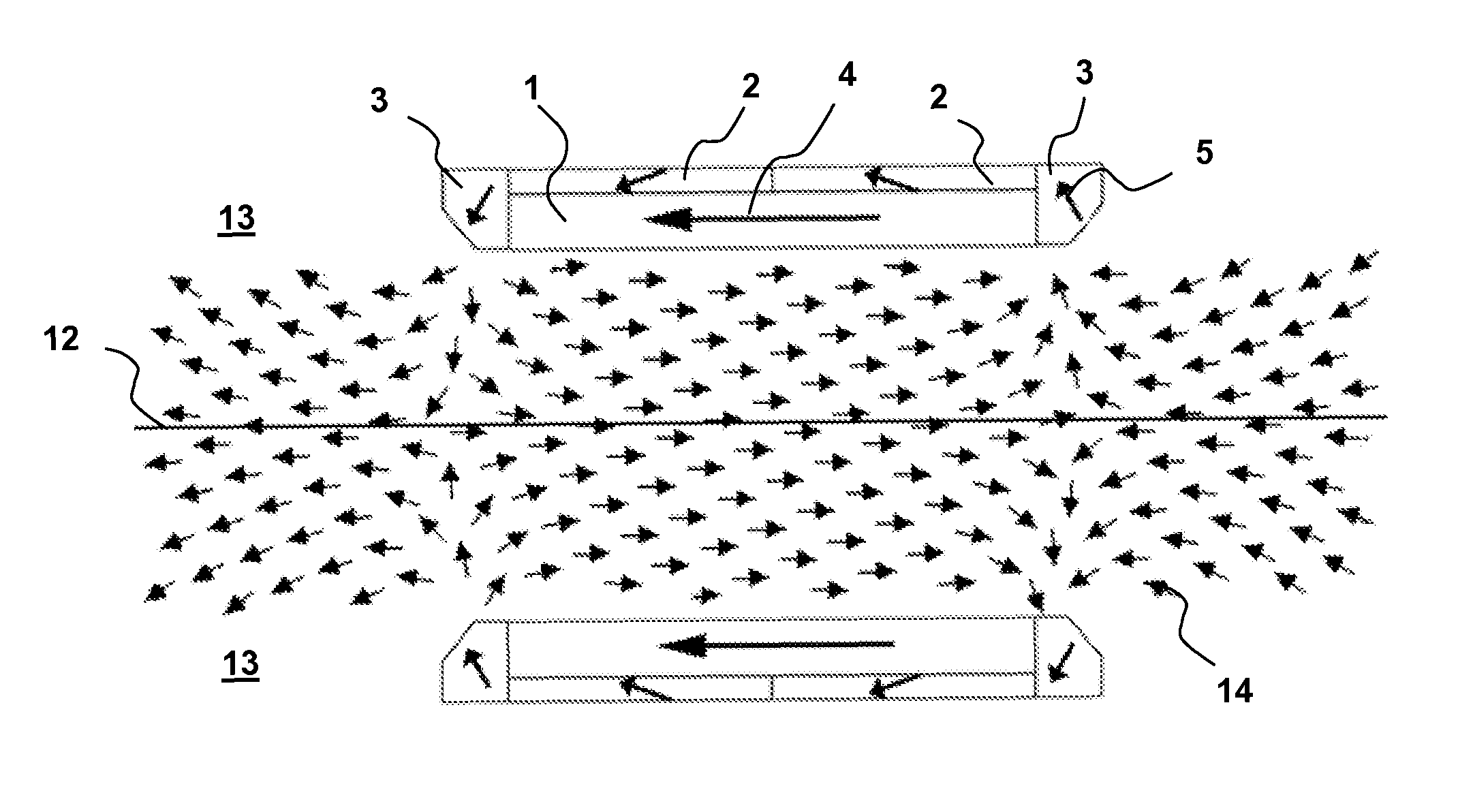
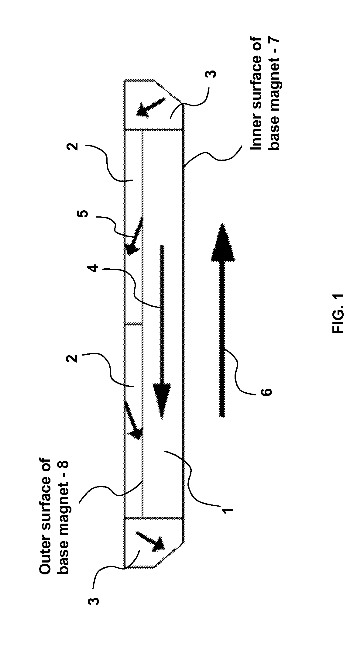
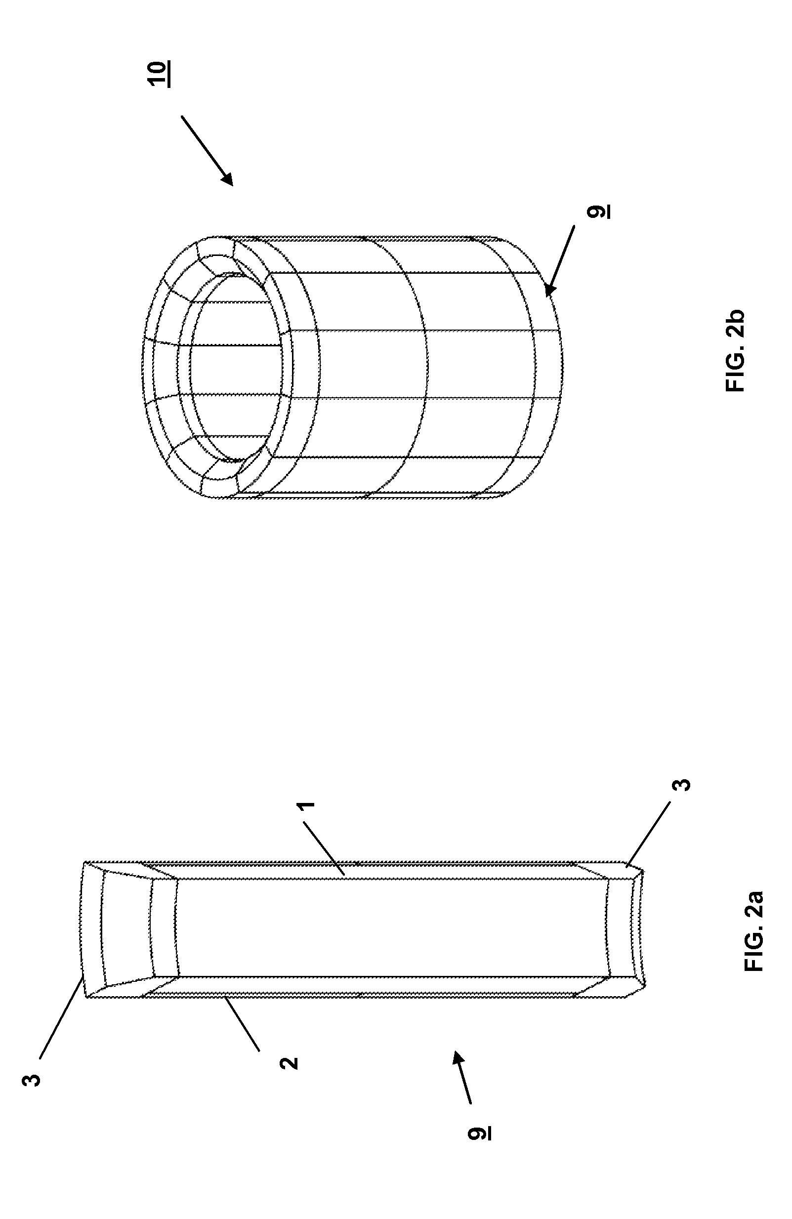
[0016]The wide aperture permanent magnet structure is comprised of two or more subassemblies Each subassembly structure is an arrangement of layered permanent magnets of varying geometry and magnetic vector alignment. FIG. 1 is a cross-sectional view of one of the magnet subassemblies. The 3-dimensional base magnet 1 is rectangular in cross-section in the long dimension. The surfaces having the long dimension extend in the longitudinal direction and may be either flat or curved. The polarity of the base magnet is indicated by the arrow 4 along the longitudinal direction. The ends of the base magnet are flat. There is an inner long dimension surface 7 defined by a straight dimension in the longitudinal direction and a straight or curved perpendicular dimension to form a flat or curved surface. A similar outer long dimension surface 8 is similarly defined and would be parallel to the inner surface. One or more first cladding magnets 2 cover the outer long dimension surface and have a ...


PUM


Abstract

A wide aperture permanent magnet structure which is useful in creating a highly uniform longitudinal or solenoidal magnetic field in the working region of the magnet and in which the aperture of the structure can be equal in cross-sectional area to the working region of the magnet. The geometry and magnetization direction of the constituent magnets are chosen to maximize the uniformity of the longitudinal or solenoidal magnetic field in the working region of the magnet while minimizing the overall volume and weight of the structure as well as eliminating the need for magnetic pole pieces made of iron or other high permeability materials. The invention can take the form of a cylindrical shell of permanent magnets to create a solenoidal magnetic field, or a parallel surface arrangement to create a longitudinal magnetic field.

Description

STATEMENT OF GOVERNMENT INTEREST[0001]The conditions under which this invention was made are such as to entitle the Government of the United States under paragraph 1(a) of Executive Order 10096, as represented by the Secretary of the Air Force, to the entire right, title and interest therein, including foreign rights.BACKGROUND OF THE INVENTION[0002]The invention relates generally to permanent magnet structures, and in particular to new permanent magnet assemblies that do not require pole pieces restricting the aperture of the working region while producing compact solenoidal or longitudinal internal magnetic working fields.[0003]Solenoidal and longitudinal magnetic fields are used extensively in the microwave tube and plasma physics communities in applications requiring the focusing and manipulation of charged particle trajectories. In the case of small microwave tubes, such as the kilowatt magnetrons used in microwave ovens, assembles of permanent magnets and high magnetic permeab...

Claims


Application Information

Patent Timeline
IPC IPC(8): H01F7/02
CPCH01F7/0278H05B6/66
Inventor HOFF, BRAD W.MARDAHL, PETER J.CHEN, CHRISTINA H.HORWATH, JOHN C.HAWORTH, MICHAEL D.
Owner THE GOVERNMENT OF THE UNITED STATES AS REPRESENTED BY THE SECREATRY OF THE AIR FORCE
Why Eureka
Try Eureka