Transmission actuator

a technology of transmission actuator and actuator, which is applied in the direction of transportation and packaging, instruments, gearing, etc., to achieve the effect of increasing accuracy

a technology of transmission actuator and actuator, which is applied in the direction of transportation and packaging, instruments, gearing, etc., to achieve the effect of increasing accuracy

US8359942B2Active Publication Date: 2013-01-29ZF CV SYST EURO BV

Image

  • Transmission actuator
  • Transmission actuator
  • Transmission actuator

Examples


Embodiment Construction

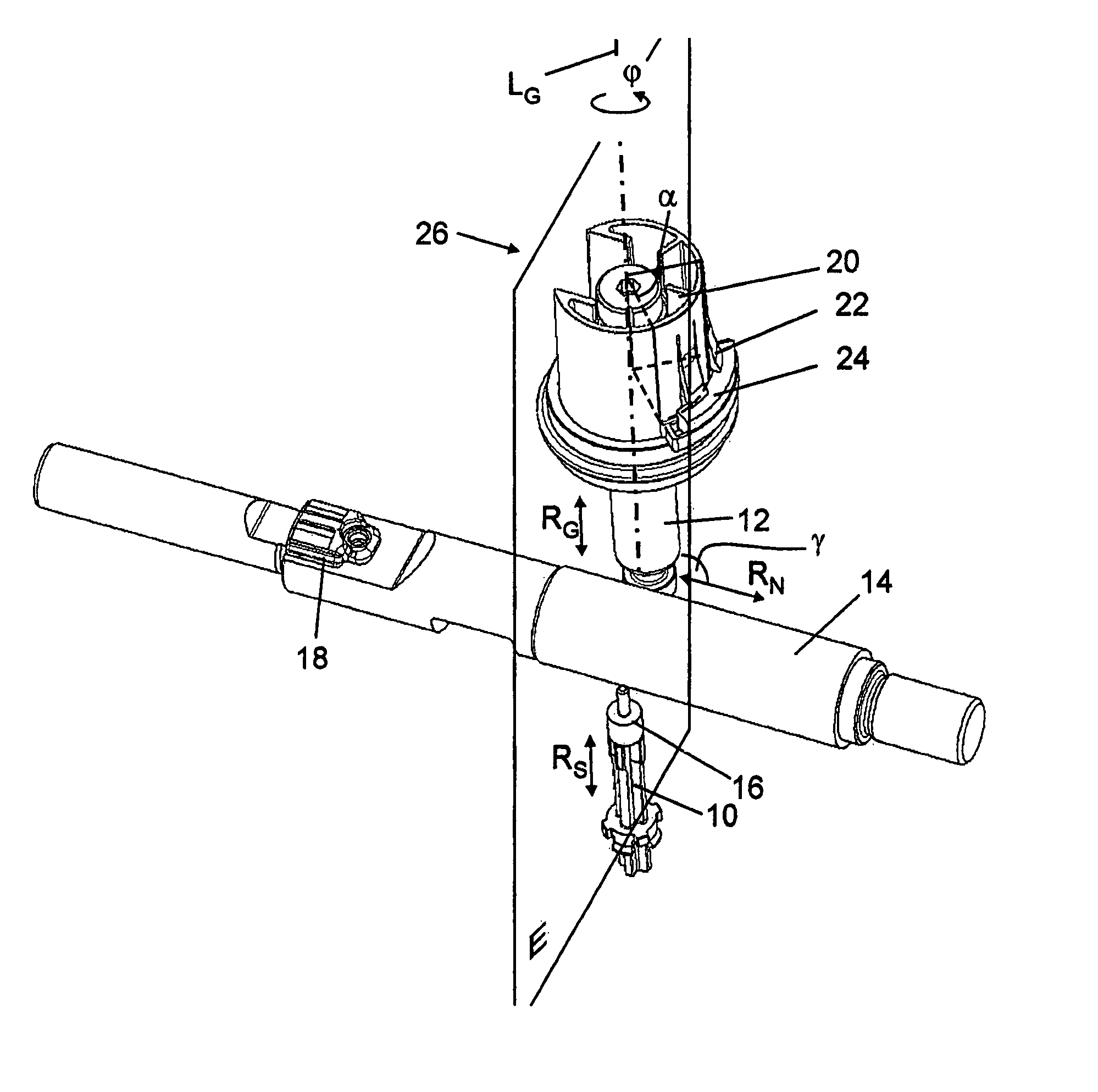
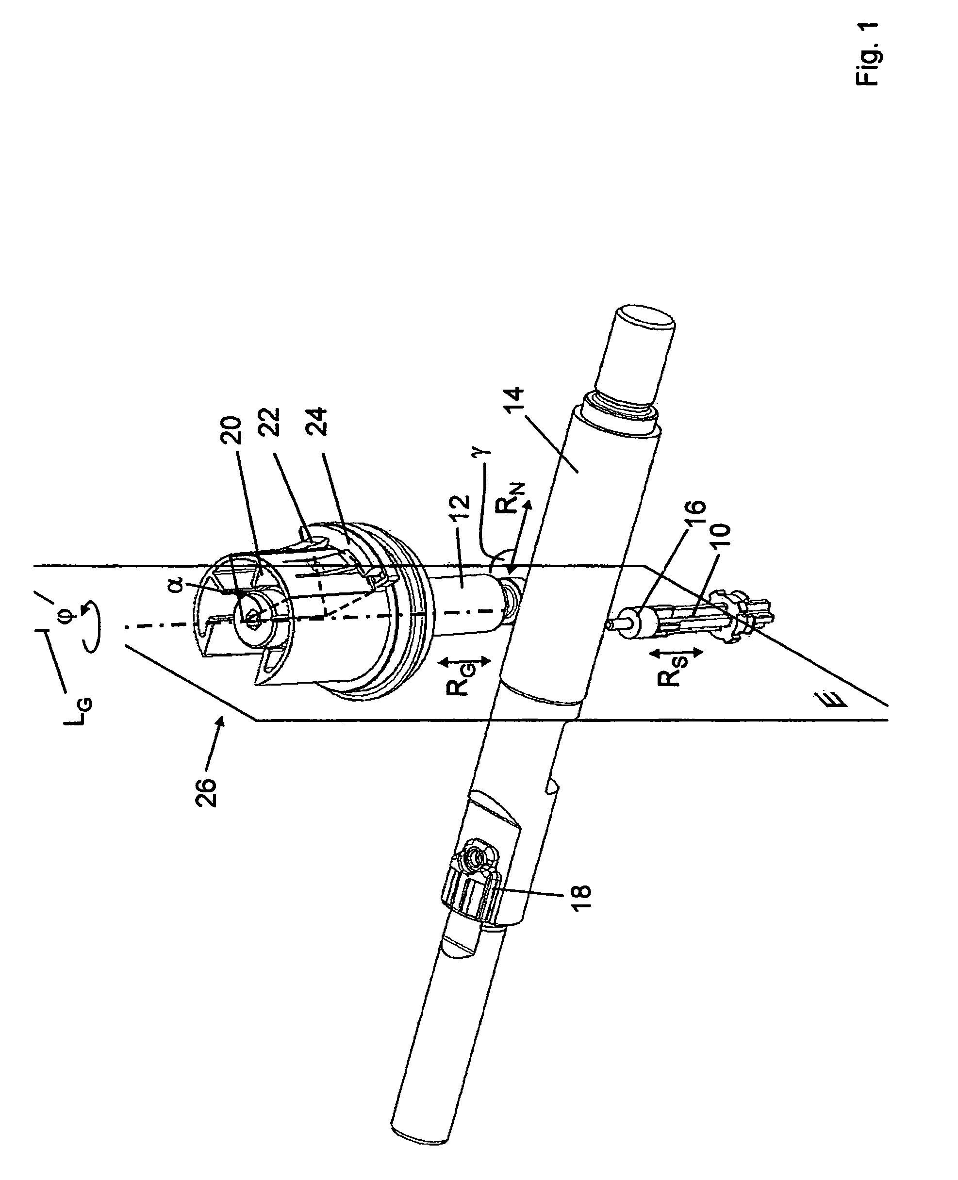
[0030]Referring now to the drawing figures, FIG. 1 shows a split stage rod 10 of a transmission (not otherwise shown), which split stage rod 10 is longitudinally movable in a split sensor measurement direction RS. FIG. 1 also shows a shift gate rod 12 mounted so as to be longitudinally movable in a shift gate sensor measurement direction RG. Also shown is a gear rod 14 mounted so as to be movable in a gear sensor measurement direction RN. The split sensor measurement device RS and the gear sensor measurement direction RG are parallel to one another and span a measurement direction plane E. The gear sensor measurement direction RN runs at an angle γ relative to the measurement direction plane E, with the angle γ in the present case being 90°, such that the gear sensor measurement direction RN runs in the normal direction with respect to the measurement direction plane E.

[0031]Arranged on the split stage rod 10 is a split sensor annular magnet 16 through which the split stage rod 10 e...


PUM


Abstract

A transmission actuator for a transmission includes a split sensor configured to detect a switching position of a split phase rod of the transmission that can be longitudinally displaced in a split sensor measuring direction. The transmission actuator further includes a gate sensor configured to detect a gate rod position of a gate rod of the transmission that can be longitudinally displaced in a gate sensor measuring direction, and a gear sensor configured to detect a gear rod position of a gear rod of the transmission that can be longitudinally displaced in a gear sensor measuring direction. Two measuring directions extend substantially parallel and span a measuring direction plane, and a third measuring direction forms an obtuse angle with the measuring direction plane.

Description

FIELD OF THE INVENTION[0001]The invention generally relates to embodiments of a transmission actuator for transmissions, including embodiments having (a) a split sensor designed to detect a shift position of a split stage rod of the transmission that is longitudinally movable in a split sensor measurement direction, (b) a shift gate sensor designed to detect a shift gate rod position of a shift gate rod of the transmission that is longitudinally movable in a shift gate sensor measurement direction, and (c) a gear sensor designed to detect a gear rod position of a gear rod of the transmission that is longitudinally movable in a gear sensor measurement direction.BACKGROUND OF THE INVENTION[0002]Transmission actuators of the general type under consideration are known and serve to detect a shift state of the transmission. Disadvantages of known transmission actuators are their complex production and cumbersome mounting on a transmission. Known transmission actuators also have a relative...

Claims


Application Information

Patent Timeline
29 Jan 2013
Publication
US8359942B2
IPC
F16H59/02; F16H61/68; F16H61/02; F16H61/70
CPC
F16H59/70; Y10T74/2003; Y10T74/19372; F16H61/70
Inventors
BRAMMER, CHRISTIAN; HEURICH, MIKE