Air admittance vent

a technology for air admittance vents and air intakes, which is applied in the direction of valve operating means/release devices, functional valve types, transportation and packaging, etc., can solve the problems of not meeting pressure differential standards, unable to balance the holding force of the spring needed to keep the vent closed, and not being able to meet the new standards. to achieve the effect of reducing the required spring for

Active Publication Date: 2013-01-29
JB PRODS
View PDF4 Cites 10 Cited by
  • Summary
  • Abstract
  • Description
  • Claims
  • Application Information

AI Technical Summary

Benefits of technology

[0004]The present invention seeks to provide an improved spring type air admittance vent that opens at very low vacuum pressures at very low pressure differentials. The AAV of this invention includes a cup shaped vent body and a vertically reciprocating valve element that seats against a valve seat that has two separate contact areas defined by an annular ridge and a conical face formed in the bottom of the vent body. When the valve element moves into its closed position, the pliable diaphragm of the valve element initially contacts the annular ridge, which forms a first part of the valve seat before moving fully into sealing contact with the conical face, which forms the second part of the valve seat. The contact with the annular ridge provides a first initial seal before the diaphragm nests into contact with the conical face to form a second seal with the valve seat. The sloped geometry of the conical face allows the valve element to self center and nest itself into a final sealed engagement, which greatly reduces the required spring force needed to maintain the proper seal. Providing a valve seat having two separate and distinct contact areas also helps to reduce the required spring force to maintain the proper seal. Consequently, the AAV of this invention can operate consistently under very low pressure differentials.

Problems solved by technology

Even though ideal for use in RVs because the valve member was held closed by the coil spring even under rough travel conditions, conventional spring type AAVs could not be made to operated under the new standards.
Various attempts were made to construct a springed AAV that would comply with the new standard, including the use of very light springs and valve elements, but were unsuccessful at balancing the holding force of the spring needed to keep the vent closed during rough travel conditions while still meeting the pressure differential standards.

Method used


Image

  • Air admittance vent
  • Air admittance vent
  • Air admittance vent

Examples


Embodiment Construction

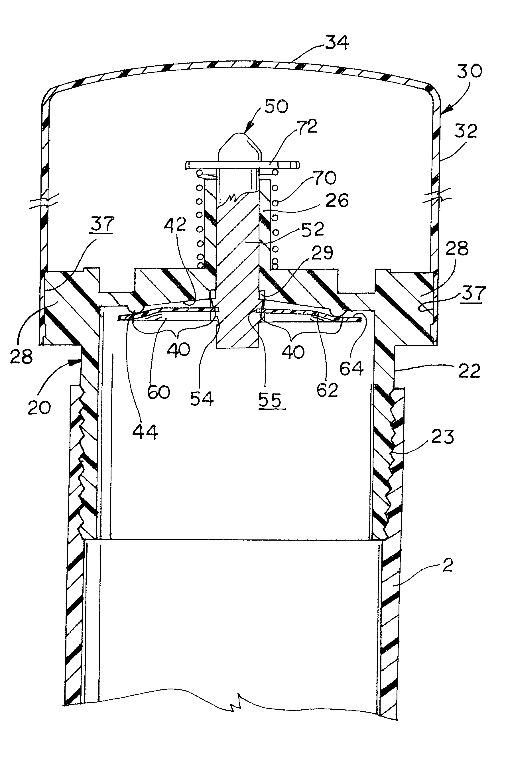
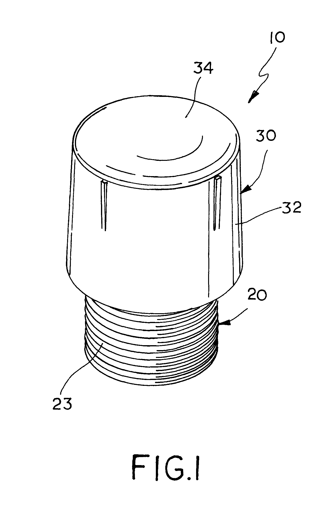
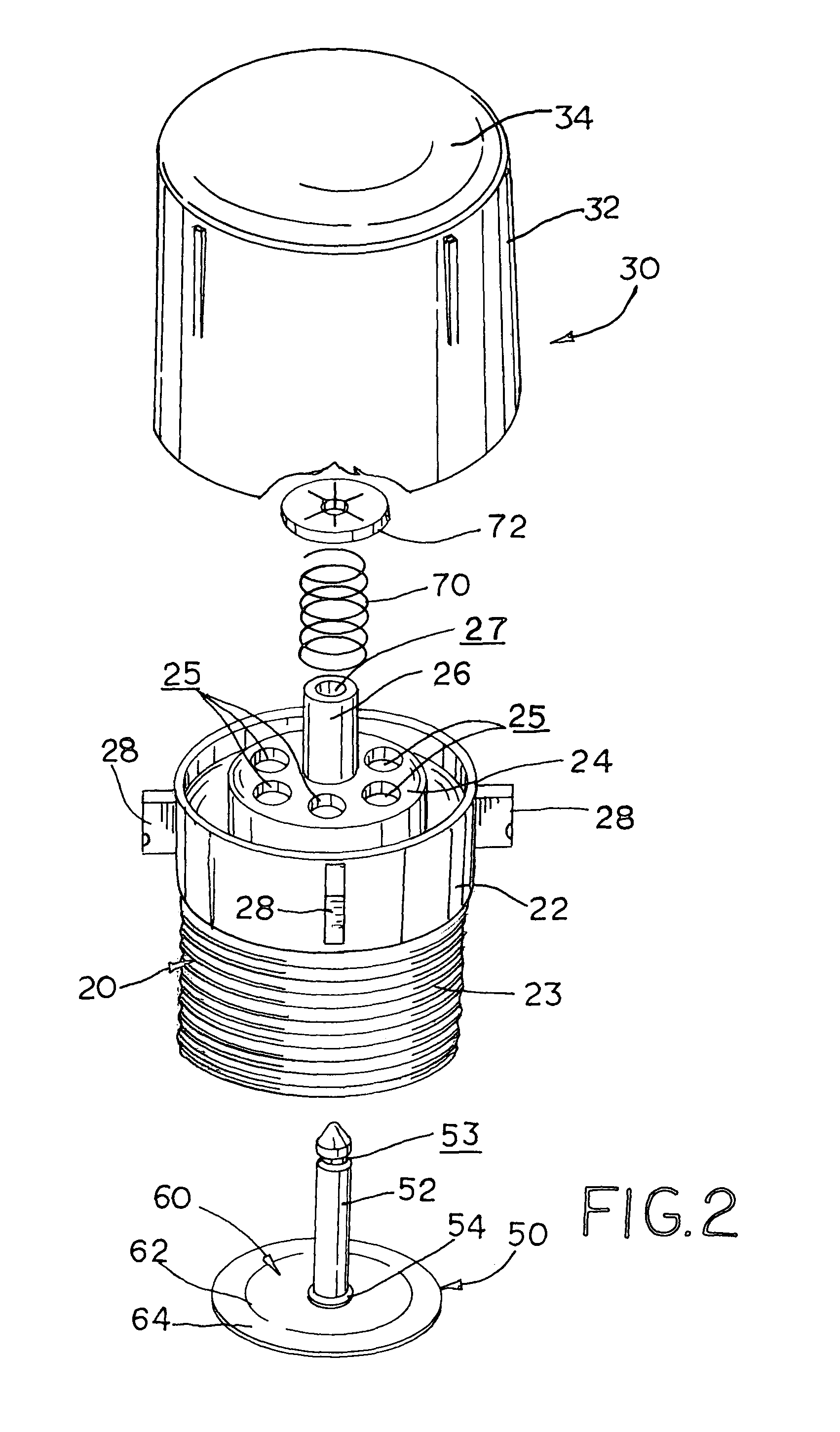
[0014]Referring now to the drawings, FIGS. 1-7 show an embodiment of the air admittance vent (“AAV”) of this invention, which is designated generally as reference numeral 10. AAV 10 includes a vent body 20, a valve element 50 and a cap 30. AAV 10 is generally configured to be mounted to the end of a vertical drain pipe. As illustrated in this embodiment of the invention, the lower portion of vent body sidewall 22 has threads 23 for mounting AAV 10 to the threaded female end of a vertical drain pipe. Vent body 20 may also be adapted and configured to be connected to a drain pipe using other conventional plumbing means known in the art within the scope of this invention.

[0015]Both vent body 20 and cap 30 are ideally constructed form a plastic material, such as nylon and are preferably formed or molded as single piece structures. Vent body 20 is generally cup-shaped and includes a cylindrical sidewall 22 and an integral upper end wall 24, which encloses the top end of the vent body and...


PUM


Abstract

The air admittance vent (“AAV”) includes a cup shaped vent body and a vertically reciprocating valve element that seats against a valve seat that has two separate contact areas defined by an annular ridge and a conical face formed in the bottom of the vent body. When the valve element moves into its closed position, the pliable diaphragm of the valve element initially contacts the annular ridge, which forms a first part of the valve seat before moving fully into sealing contact with the conical face, which forms the second part of the valve seat. The contact with the annular ridge provides a first initial seal before the diaphragm nests into contact with the conical face to form a second seal with the valve seat.

Description

[0001]This invention relates to an air admittance vent and in particular an air admittance valve for use in recreational vehicles.BACKGROUND OF THE INVENTION[0002]Air admittance vents (“AAVs”) are used in a variety of plumbing systems to prevent the escape of unwanted gases through drain pipes. AAVs are vertically connected to the drain pipes and supplement the vertical vent pipe in large plumbing systems. AAVs open under the vacuum created in the drain by the flow of water through the drain pipe and close when the water is no longer flowing through the drain.[0003]Spring type AAVs, such as the plumbing vent valve described in U.S. Pat. No. 3,604,132, use a coil spring to hold the valve member closed. For many years, the spring type of AAVs were commonly used in the plumbing systems of recreational vehicles (“RVs”), as well as, in residential and commercial plumbing systems. The coil spring facilitated valving mechanism ensured that the vents remained closed while the RV moved even ...

Claims


Application Information

Patent Timeline
Patent Type & Authority Patents(United States)
IPC IPC(8): F16K15/14
CPCF16K24/06F16K15/148E03C1/1225E03F5/08Y10T137/7762Y10T137/7931Y10T137/7897Y10T137/789F16K15/1481F16K15/161
Inventor CASHEN, STEVEN W.CHRISTMAN, RANDOLPH J.DELAHANTY, PATRICK D.SEARING, SR., MAYNARD R.SEARING, G. SCOTTKROLZICK, FRED
Owner JB PRODS
Why Eureka
Try Eureka