Method and apparatus for the treatment of scoliosis

a technology for scoliosis and treatment methods, applied in the field of scoliosis treatment methods, can solve the problems of insufficient kyphosis in the central part of the spine, inability to fully correct a three-dimensional deformity, and inability to allow the patient to retain a full range of motion

Inactive Publication Date: 2015-05-21
HODGSON BRUCE FRANCIS
View PDF66 Cites 3 Cited by
  • Summary
  • Abstract
  • Description
  • Claims
  • Application Information

AI Technical Summary

Benefits of technology

[0020]It is an object of the present invention to provide an alternative method for treatment of scoliosis and an apparatus for enabling the method. The invention may also provide a treatment

Problems solved by technology

However, where at least one vertebra is not sufficiently wedge-shaped, but too rectangular, the spine does not curve normally at that point.
This most frequently results in insufficient kyphosis in the central part of the spine.
Known systems incorporating tethers or telescoping rods correct spinal deformity in one plane only, that of the restricting action provided by the construct or imparted by a corrective force applied, and do not fully correct a three-dimensional deformity.
These systems may not al

Method used


Image

  • Method and apparatus for the treatment of scoliosis
  • Method and apparatus for the treatment of scoliosis
  • Method and apparatus for the treatment of scoliosis

Examples


first preferred embodiment

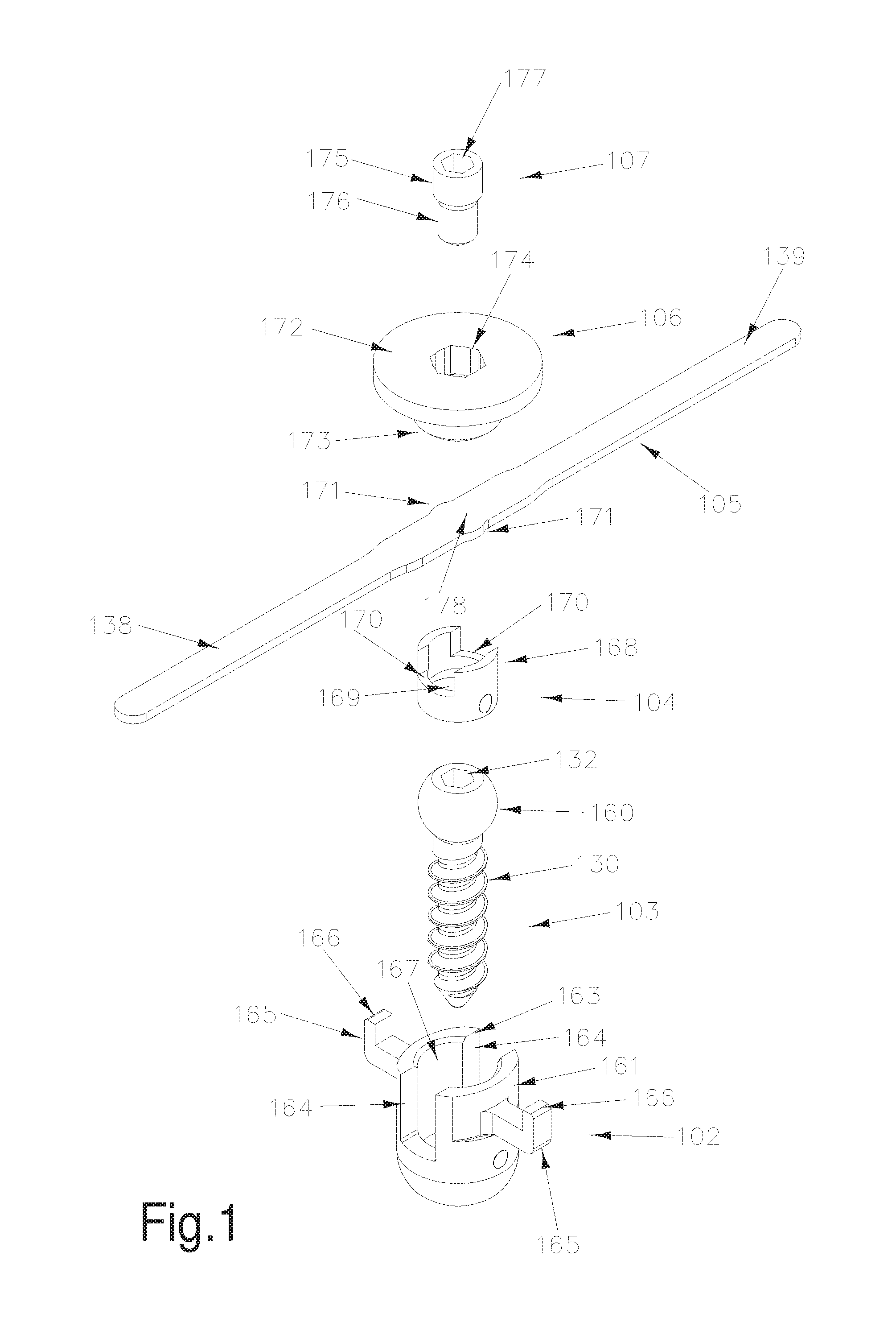
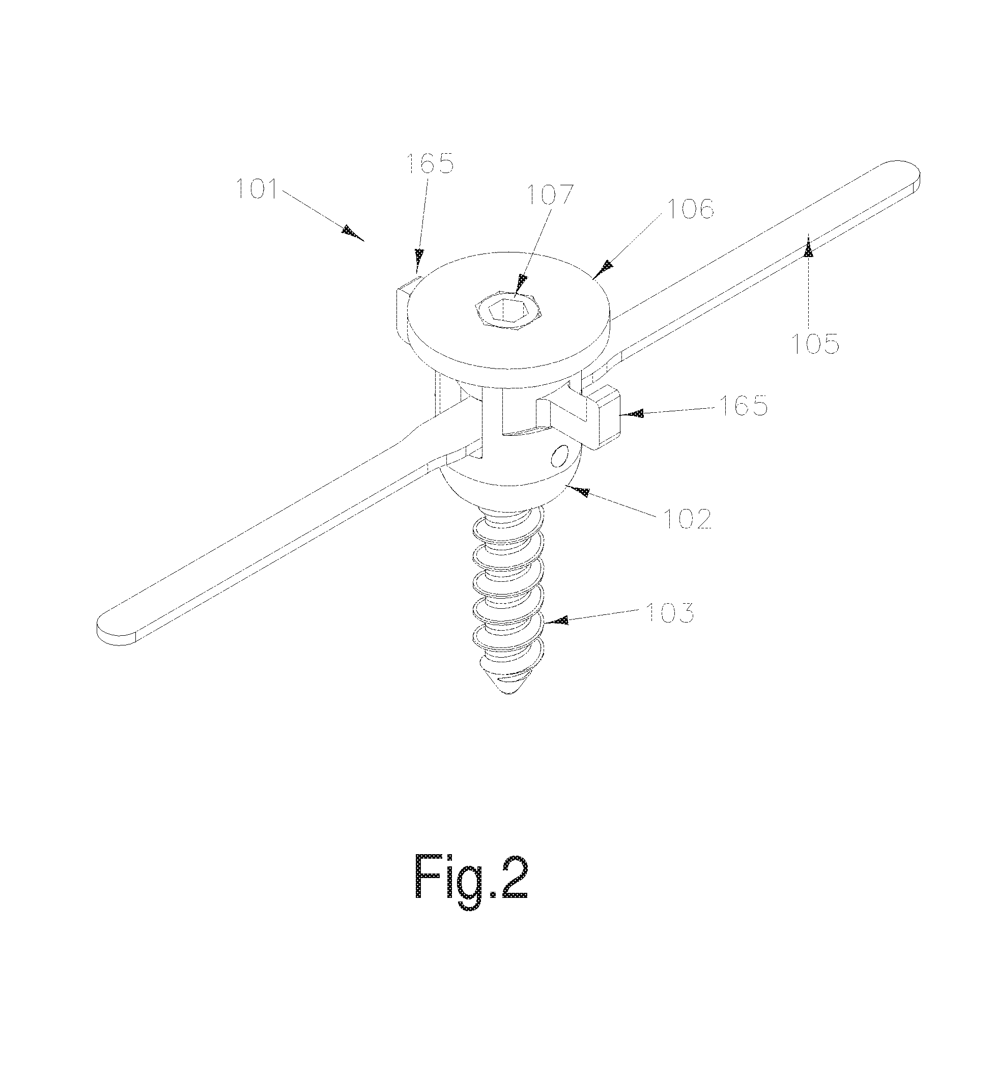
[0079]FIGS. 1, 2 and 3 show a first preferred embodiment of an implant module 101 which is part of the apparatus of the present invention.

[0080]The implant module 101 includes a cage 102, a pedicle screw 103, a spring socket 104, spring 105, spring cap 106 and tensioner 107. Each part of the implant module is made of biologically inert, sterilisable materials suitable for implantation in a live host.

[0081]Pedicle screw 103 is similar to a well-known type including a screw threaded column 130 adapted to engage with a pedicle of a vertebra. At a first end of column 130, a rounded screw head 160 is provided with tool engagement means, preferably in the form of a screw tool cavity 132 adapted to receive a tool, e.g. an Allen key. Engagement of an appropriate known type of tool with these tool engagement means will allow rotation of the screw 103, and therefore engagement of column 130 with a pedicle.

[0082]Screw 103 may be similar to any of the many different commercially available spina...

second preferred embodiment

[0104]FIG. 5 and FIG. 6 show two different views of a second embodiment of an implant module 201 which is a part of the apparatus of the present invention.

[0105]The implant module 201 includes a pedicle screw 203, similar to a well known type including a screw threaded column 230 adapted to engage with a pedicle of a vertebra. The column 230 is co-axial with a screw-threaded shaft 233. To allow for screwing the screw 203 into a pedicle, tool engagement means may be provided on or adjacent the shaft 233. These tool engagement means may include external flats 231 and / or a screw tool cavity 232 adapted to receive a tool, e.g. an Allen key. Engagement of an appropriate known type of tool with either of these tool engagement means will allow rotation of the screw 203, and therefore engagement of column 230 with a pedicle.

[0106]Screw 203 may be similar to any of the many different commercially available spinal screws. In alternative embodiments, the pedicle screws 203 may be replaced with...

third embodiment

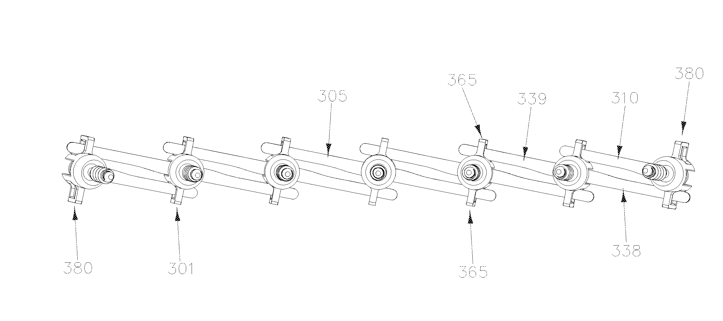
[0124]FIG. 7 and FIG. 8 show two different views of a third embodiment of an implant module 301 which is a part of the apparatus of the present invention.

[0125]The implant module 301 includes a cage 302, a pedicle screw 303, a spring socket 304, spring 305, and connection means 307. Pedicle screw 303 includes a screw threaded column 330 adapted to engage with a pedicle of a vertebra. At a first end of column 330, a rounded screw head 360 is provided with tool engagement means, preferably in the form of a screw tool cavity 332 adapted to receive a tool, e.g. an Allen key.

[0126]Cage 302 has an essentially cylindrical cage body 361, with a central bore 362 dimensioned such that screw threaded column 330 of pedicle screw 303 passes therethrough and the screw threaded column 330 extends from a first end of the cage body 361, but the rounded screw head 360 is retained within the bore 362 of the cylindrical cage body 361.

[0127]The sidewall of the cage body 361 includes two cage spring slot...


PUM


Abstract

Spinal adjustment system including at least three implant modules, at least one of the implant modules being a first implant module including:
    • means for engaging the first implant module with a first vertebra; and
    • first force application means;
characterised in that:
  • the first force application means is adapted to engage with a second implant module engaged with a second vertebra superior to the first vertebra;
  • the first force application means is adapted to also engage with a third implant module engaged with a third vertebra inferior to the first vertebra; and
  • the first implant module includes means of adjusting the force applied to the first vertebra by the first force application means.
  • Description

    FIELD OF THE INVENTION[0001]The present invention is a method of treatment of scoliosis and an apparatus for applying this new method.BACKGROUND[0002]Any discussion of the prior art throughout the specification is not an admission that such prior art is widely known or forms part of the common general knowledge in the field.[0003]Scoliosis is a medical condition in which a person's spine has a deformity which causes the spine to be primarily curved from side to side; it may also be rotated along its axis. On an x-ray, when taken from the front or back of the spine of an individual with a typical scoliosis, the spine may take the form of an “S” or a “C” rather than a straight line. It is typically classified as congenital (caused by vertebral anomalies present at birth), idiopathic (sub-classified as infantile, juvenile, adolescent, or adult according to when onset occurred) or as having developed as a secondary symptom of another condition, such as cerebral palsy, spinal muscular at...

    Claims


    Application Information

    Patent Timeline
    IPC IPC(8): A61B17/70
    CPCA61B17/7053A61B17/7035A61B17/7001A61B17/7005A61B17/701A61B17/7032A61B17/7037A61B17/70
    Inventor HODGSON, BRUCE FRANCISMCMILLAN, IAIN ALEXANDERMORRISON, PAUL JOHNDAVIS, SIMON JOHN
    Owner HODGSON BRUCE FRANCIS
    Why Eureka
    Try Eureka