Expansion valve
a valve opening degree and valve opening technology, applied in the field of expansion valves, can solve the problems of difficulty in maintaining the characteristic of the valve opening degree within a predetermined characteristic range, and achieve the effect of simple adjustment and increased cos
- Summary
- Abstract
- Description
- Claims
- Application Information
AI Technical Summary
Benefits of technology
Problems solved by technology
Method used
Image
Examples
second embodiment
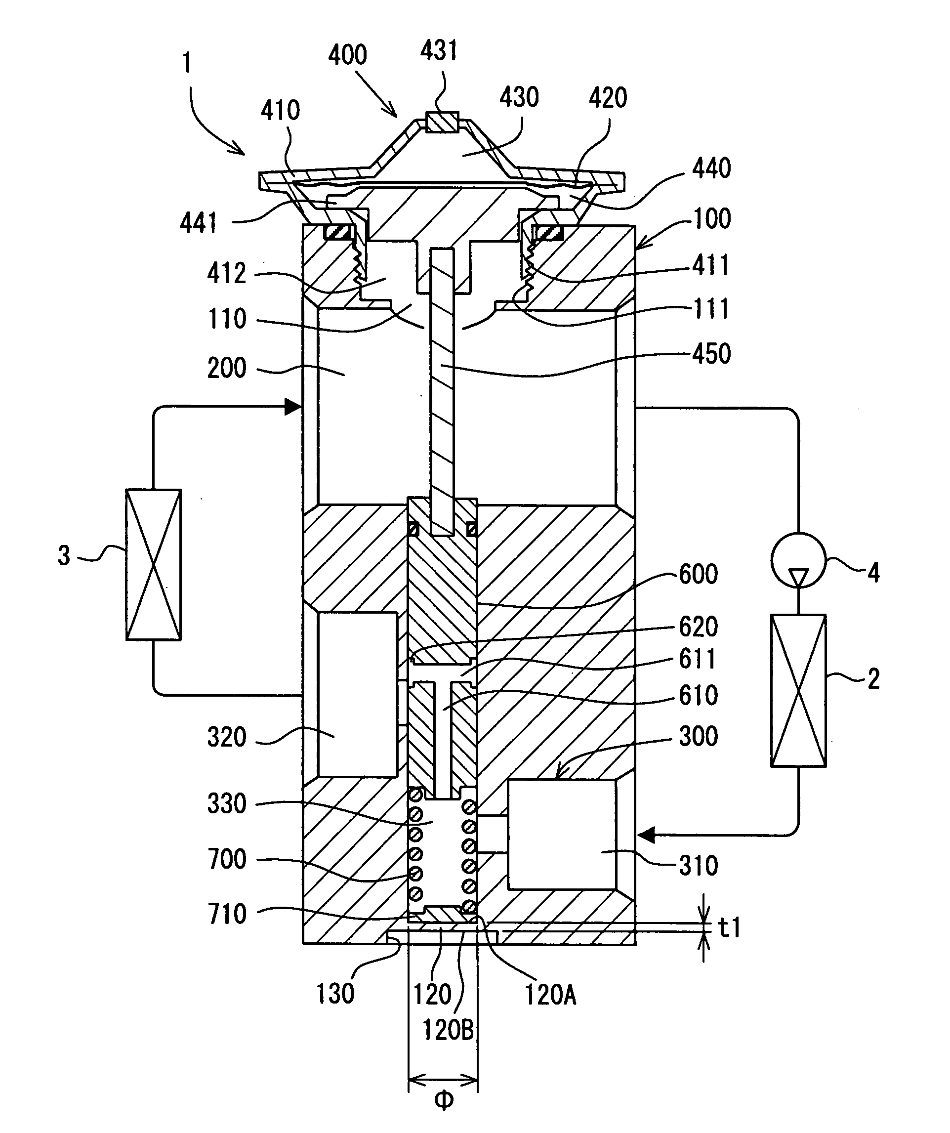
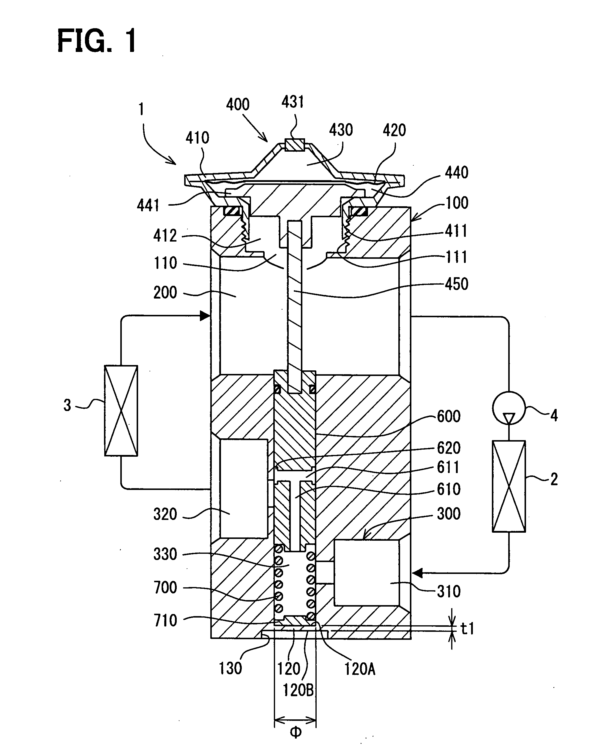
[0070]A second embodiment will be described with reference to FIG. 4. In this embodiment, the deformation portion 120 is formed on the bottom wall of the main body block 100. The working surface 120B is provided by a portion of the bottom surface of the main body block 100. The main body block 100 has a tubular projection 140 that extends from the working surface 120B. The tubular projection 140 has a female thread portion 140A on its inner surface, so that the adjustment jig 800 is screwed into the tubular projection 140. The tubular projection 140 is integrally formed with the main body block 100 when the main body block 100 is formed.
[0071]The tubular projection 140 serves an operation portion for displacing the deformation portion 120 in at least one of the upward direction and the downward direction. For example, the tubular projection 140 is located at a center of the deformation portion 120. The tubular projection 140 extends in a direction parallel to the displacement direct...
third embodiment
[0075]A third embodiment of the present invention will be described with reference to FIG. 5. In this embodiment, the main body block 100 has the recessed portion on its bottom, and the deformation portion 120 is provided by the wall that defines the recessed portion. As shown in FIG. 5, the peripheral wall 130 is formed with a female thread portion 130A to which the male thread portion 800A of the adjustment jig 800 is screwed.
[0076]Here, the depth of the recessed portion is greater than that of the first embodiment. Further, the depth of the recessed portion is greater than the diameter of the deformation portion 120.
[0077]The deformation portion 120 is deformed in the upward direction by screwing the adjustment jig 800 into the recessed portion. In this case, the deformation portion 120 can be deformed by a force that is smaller than the force required to simply moving the adjustment jig 800 as the first embodiment. As such, the deformation portion 120 is easily deformed by a sma...
fourth embodiment
[0078]A fourth embodiment will be described with reference to FIG. 6. As shown in FIG. 6, the main body block 100 is formed with an opening portion 150 on its bottom end. The opening portion 150 is located at the bottom of the small diameter passage portion 330 and is in communication with the small diameter passage portion 330. The opening portion 150 is coaxial with the small diameter passage portion 330 and has an inner diameter larger than the inner diameter of the small diameter passage portion 330. Namely, the opening portion 150 is formed at a position opposite to the spool valve 600 and the inner diameter of the opening portion 150 is larger than the outer diameter of the spring member 700.
[0079]Further, a deformation plate member 160 having a shape corresponding to an inner shape of the opening portion 150 is fixed in the opening portion 150 such as in a pressed manner. For example, the deformation plate member 160 has a substantially cup shape. The deformation plate member...
PUM
 Abstract
Description
Claims
Application Information
 - R&D
- Intellectual Property
- Life Sciences
- Materials
- Tech Scout
- Unparalleled Data Quality
- Higher Quality Content
- 60% Fewer Hallucinations
Browse by: Latest US Patents, China's latest patents, Technical Efficacy Thesaurus, Application Domain, Technology Topic, Popular Technical Reports.
© 2025 PatSnap. All rights reserved.Legal|Privacy policy|Modern Slavery Act Transparency Statement|Sitemap|About US| Contact US: help@patsnap.com


