Valve stem seal

A technology of sealing device and valve device, which is applied in the direction of valve device, shaft seal, valve lift, etc., can solve problems such as leakage, and achieve the effects of avoiding leakage, reducing friction loss, and reducing friction

Active Publication Date: 2013-04-10
AB SKF
View PDF7 Cites 4 Cited by
  • Summary
  • Abstract
  • Description
  • Claims
  • Application Information

AI Technical Summary

Problems solved by technology

As a result, the sealing lip can only compensate for small radial play, which can therefore still lead to "cross-blow" if there is already a small radial play between the valve stem and valve guide or if there is a misalignment

Method used


Image

  • Valve stem seal

Examples


Embodiment Construction

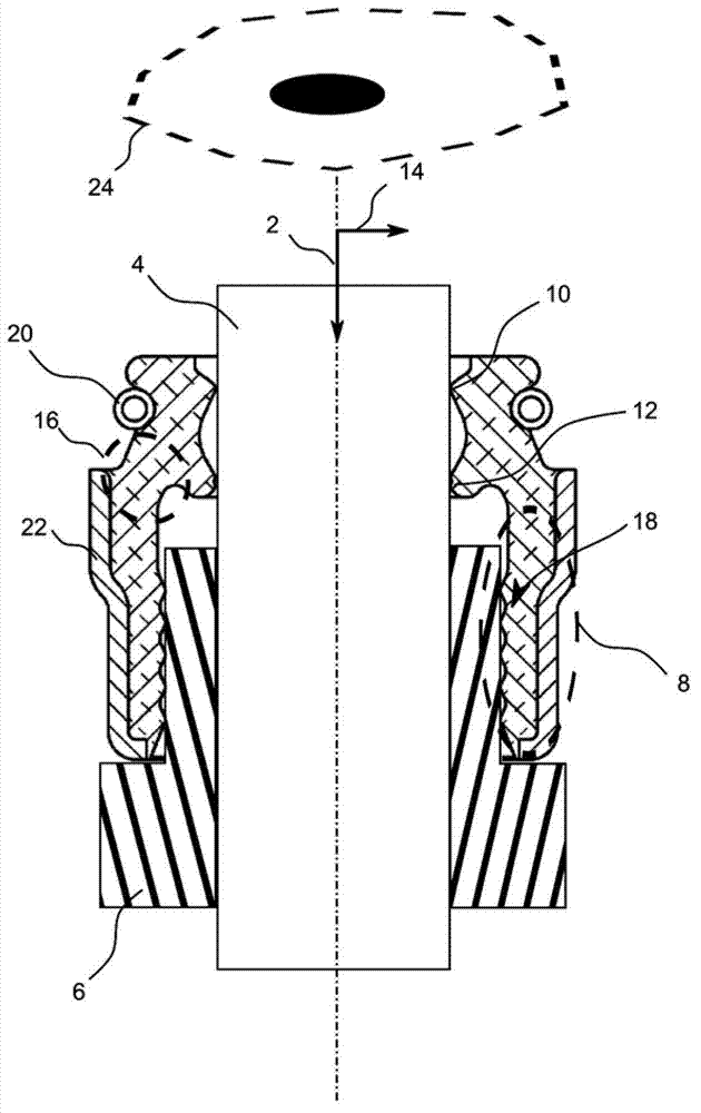
[0015] figure 1 The stem seal is shown in the installed condition. The valve stem sealing device is used for sealing the valve stem 4 moving along the axial direction 2 . The valves or valves are usually operated counter to the axial direction 2 and are not shown here for the sake of clarity, eg cam actuation. Movement along the axis 2 opens a valve crown or disc connected to the valve stem 4 on the extension of the axis 2 to open the inlet or outlet of the combustion chamber of the vehicle engine. As for the valve top or the valve disc and other mechanisms, for the sake of clarity of view, they are not shown and described in detail here, because those skilled in the art are well aware of them.

[0016] The valve stem 4 is guided by a valve guide 6 whose inner diameter or through hole matches the outer diameter of the valve stem 4 and is used to achieve or determine the linear movement of the valve stem 4 . Due to unavoidable manufacturing tolerances, there is a radial axia...


PUM


Abstract

A valve stem seal (1) seals a valve stem (4) that is reciprocally movable in an axial direction. The valve stem seal includes a base body (8) that is connectable with a valve stem guide (6). A first seal lip (10) is resiliently positioned relative to the base body via an elastic connection (16) and seals the valve stem relative to an oil chamber (24). A second seal lip (12) is spaced in the axial direction (2) from the first seal lip and seals the valve stem relative to a gas chamber. The second seal lip is also resiliently positioned relative to the base body via the elastic connection.

Description

technical field [0001] The invention relates to a valve stem seal which, inter alia, takes account of the recent development trend of increasingly higher requirements in terms of oil-tightness and gas-tightness. Background technique [0002] Valve stem seals or valve stem seals are used in various internal combustion engines, for example in passenger cars, vans or motorcycles, for valves circulating in valve covers or valve covers, for lubricating camshafts or similar structures It keeps the necessary oil away from the combustion chamber and intake pipe, and prevents high-pressure exhaust gas or mixed gas from entering the valve cover when the valve or valve is open. [0003] As turbochargers and compressors are increasingly used in passenger cars, the gas pressure at the end of the valve or valve stem seal facing the cylinder is significantly greater than the ambient pressure in the valve cover. As a result, there is an increasing risk of so-called "cross-leakage", ie the ...

Claims


Application Information

Patent Timeline
Patent Type & Authority Applications(China)
IPC IPC(8): F16K41/04
CPCF01L3/08F16K1/32F16K41/04
Inventor J.库尔思J.内泽尔
Owner AB SKF
Why Eureka
Try Eureka