
Rotary striking tool

a rotary and tool technology, applied in the field of rotary striking tools, can solve the problems of complicated electrical wiring and high cost of tools, and achieve the effect of accurately detecting the rotation angl

Inactive Publication Date: 2013-01-29
KOKI HLDG CO LTD
View PDF13 Cites 31 Cited by
  • Summary
  • Abstract
  • Description
  • Claims
  • Application Information

AI Technical Summary

Benefits of technology

[0008]One object of the invention is to provide a rotary striking tool which can accurately detect the rotation angle of an output shaft at the striking operation even if an angular sensor is not provided at the output shaft.

Problems solved by technology

As a result, the impact tool is enlarged to provide the angular sensor and the rotary transformer etc., whereby electric wiring becomes complicated and the tool becomes expensive.

Method used


Image

  • Rotary striking tool
  • Rotary striking tool
  • Rotary striking tool

Examples


embodiment 1

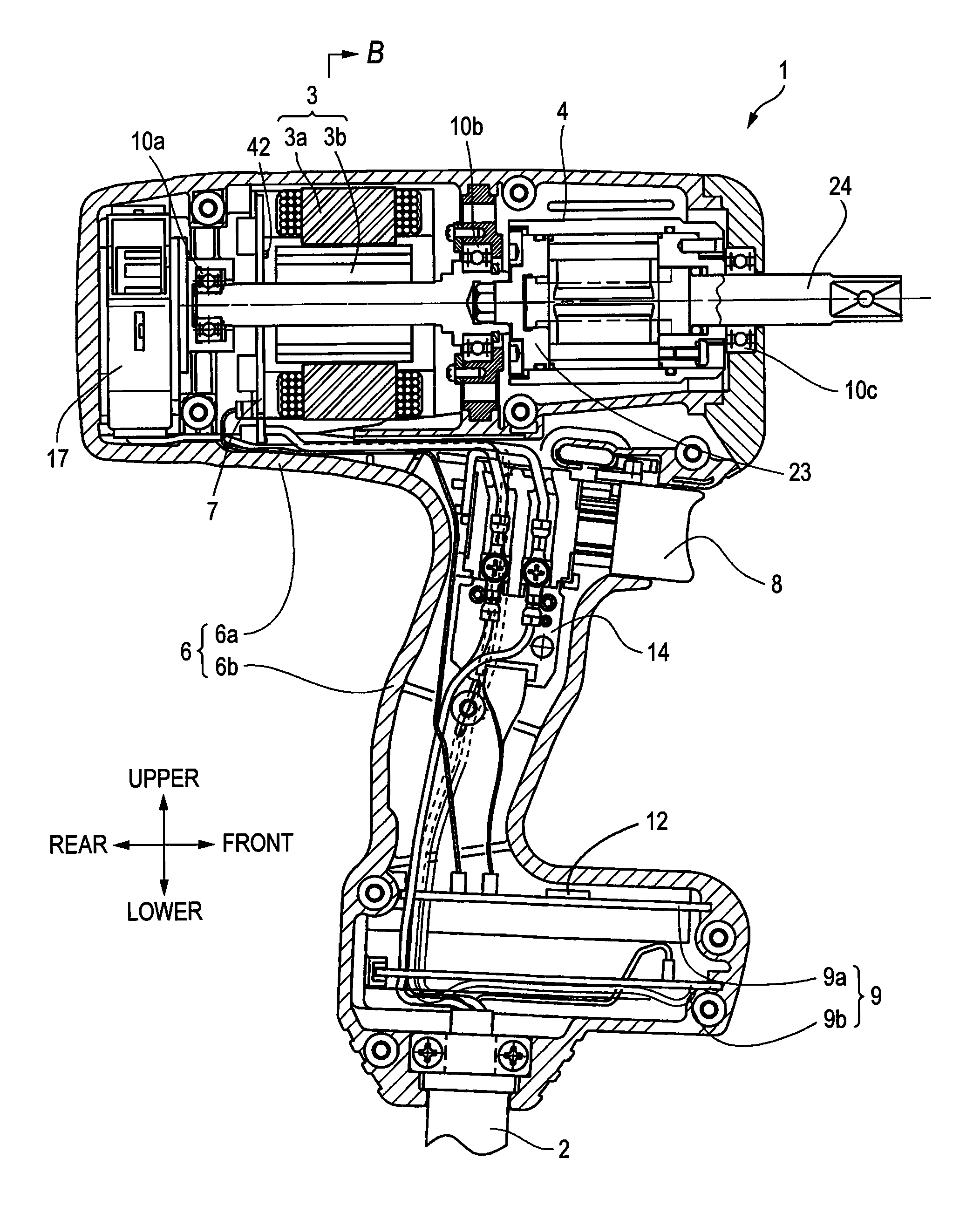
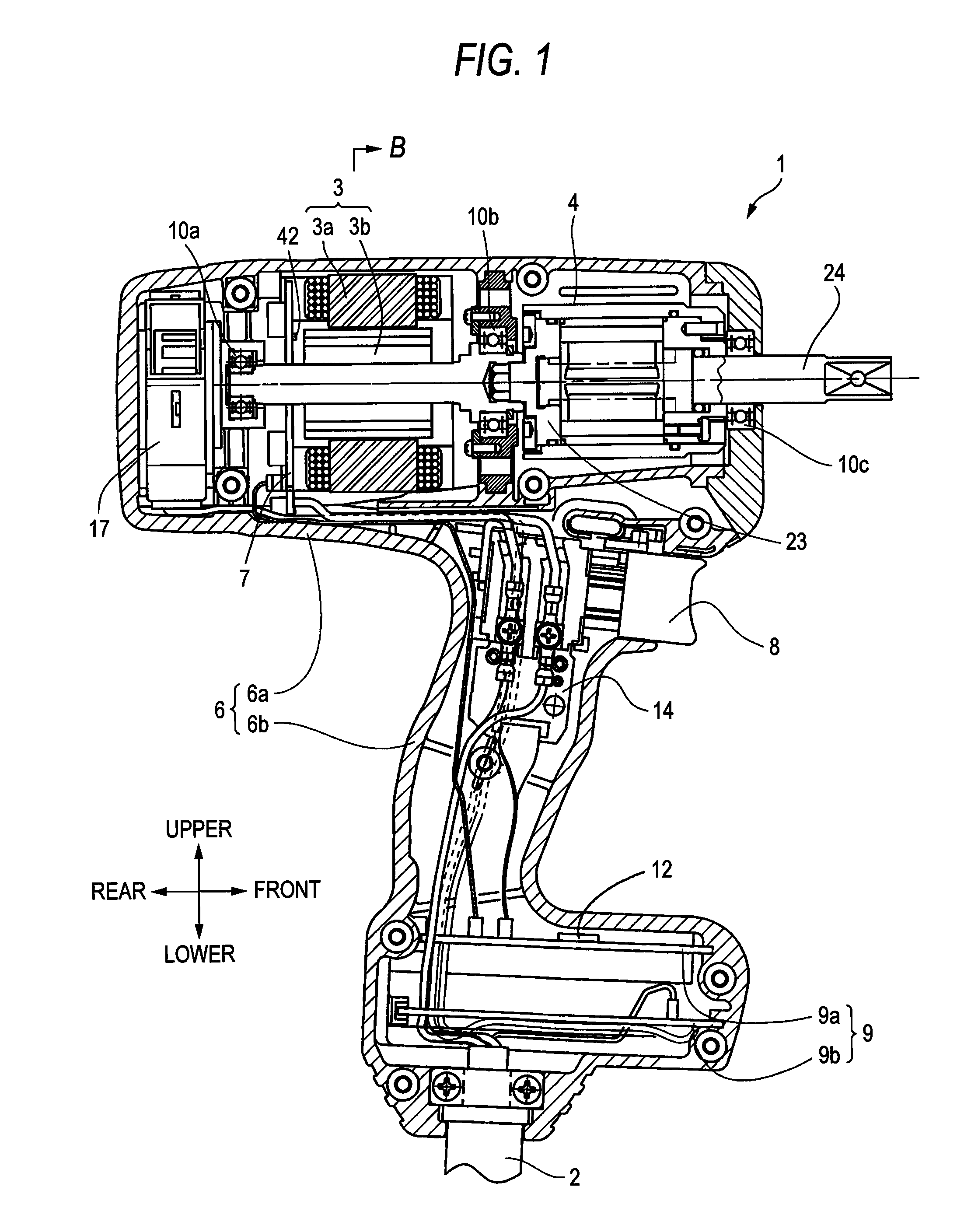
[0037]Hereinafter, the embodiment will be explained with reference to drawings. In this embodiment, an impact driver using an oil pulse unit is exemplified as a rotary striking tool. FIG. 1 shows the impact driver according to the embodiment. In the specification, directions of upper, lower, forward and rear will be explained as being coincident with the directions of upper, lower, forward and rear shown in FIG. 1, respectively.

[0038]The impact driver 1 performs a fastening procedure for fastening a screw, a nut, a bolt etc. In the fastening procedure, a motor 3 is driven by electric power supplied via a power supply cable 2 from the outside, and then the motor 3 drives an oil pulse unit 4 to apply a rotation force and an impact force to the main shaft of the oil pulse unit 4 to thereby continuously / intermittently transmit a rotation striking force to a not-shown tip tool such as a driver bit, a hexagonal socket etc.

[0039]The electric power supplied to the power supply cable 2 is a ...


PUM


Abstract

According to an aspect of the present invention, there is provided a rotary striking tool, including: a motor; an impact unit having a driving part being driven by the motor and an output part; a tip-tool side output shaft that is coupled to the output part; an impact detection unit that detects an impact generated at the impact unit; and a control unit programmed to: control the impact unit to perform a confirmation striking when the impact detected by the impact detection unit reaches a prescribed value, detect a rotation angle of the output shaft at the confirmation striking, determine whether a fastening operation is completed when the detected rotation angle is equal to or smaller than a predetermined angle, and continue the fastening operation when the detected rotation angle is larger than the predetermined angle.

Description

CROSS-REFERENCE TO RELATED APPLICATION(S)[0001]This application is based upon and claims priority from Japanese Patent Application No. 2009-230037 filed on Oct. 1, 2009, the entire contents of which are incorporated herein by reference.BACKGROUND[0002]1. Field of the Invention[0003]An aspect of the present invention relates to a rotary striking tool which is driven and rotated by a motor to thereby fasten a fastening member such as a screw or a bolt by using an intermittent striking force.[0004]2. Description of the Related Art[0005]As a rotary striking tool (driving tool), an impact tool which fastens a screw or a bolt etc. by applying a rotation force or a rotational-direction striking force is known. JP-2005-305578-A discloses an impact driver as the kinds of the rotary striking tool. Further, there is known an oil pulse tool using an oil pulse unit as a striking mechanism. In the impact driver disclosed in JP-2005-305578-A, a hummer part rotates while being axially-movable by us...

Claims


Application Information

Patent Timeline
Patent Type & Authority Patents(United States)
IPC IPC(8): B25B23/14
CPCB25B23/1405B25B23/1475
Inventor IIMURA, YOSHIOISHIMARU, KENROIWATA, KAZUTAKATAKANO, NOBUHIRO
Owner KOKI HLDG CO LTD
Learn More