Compliant conduit connector

a conduit connector and connector technology, applied in the direction of couplings, screw threaded joints, mechanical equipment, etc., can solve the problems of inability to move in a wide range of motion of prior art couplings, and achieve the effect of preventing wear or galling of the sealing surface and effective sealing

Active Publication Date: 2013-01-29
EATON INTELLIGENT POWER LTD
View PDF31 Cites 20 Cited by
  • Summary
  • Abstract
  • Description
  • Claims
  • Application Information

AI Technical Summary

Benefits of technology

[0008]Significantly, the exemplary compliant connector system provides for contact between an o-ring and a sealing surface area of the inner surface of the socket formed on the first conduit where the sealing surface does not come in contact with the bearing channels or the seal channel. This geometry prevents the wear or galling of the sealing surface so that the o-ring can maintain an effective seal.

Problems solved by technology

However, these prior art couplings do not allow the wide range of motion allowed by the exemplary compliant conduit connector system.

Method used


Image

  • Compliant conduit connector
  • Compliant conduit connector
  • Compliant conduit connector

Examples


Embodiment Construction

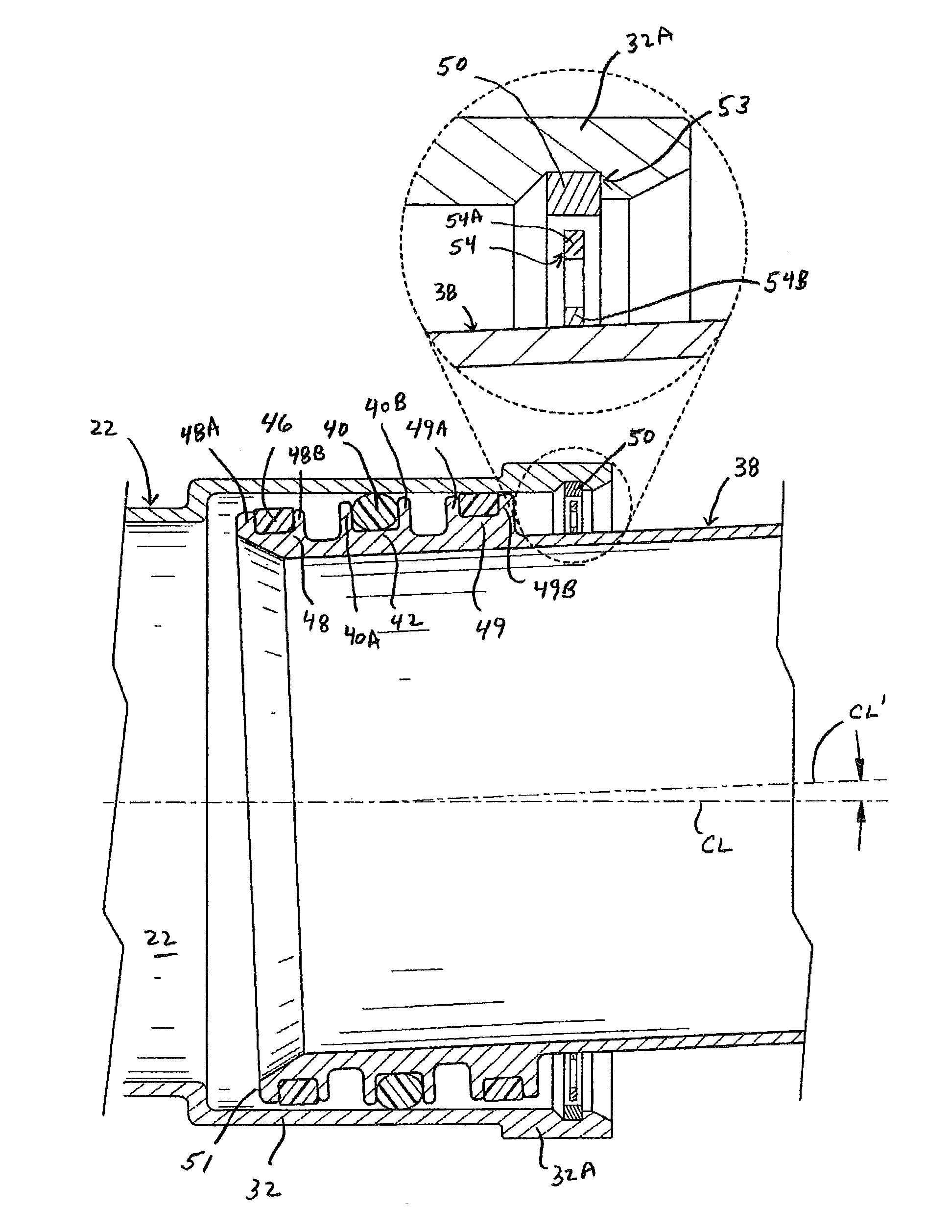
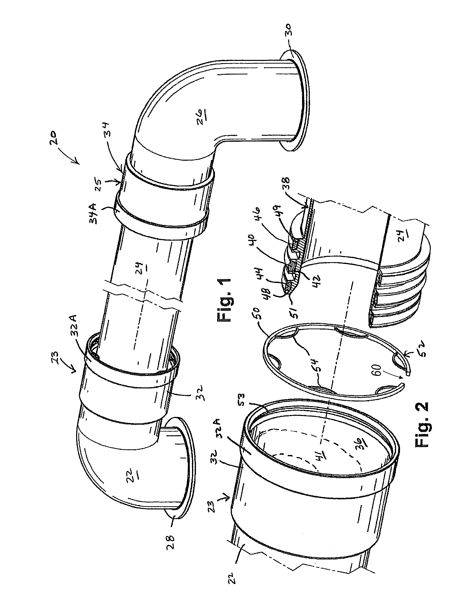
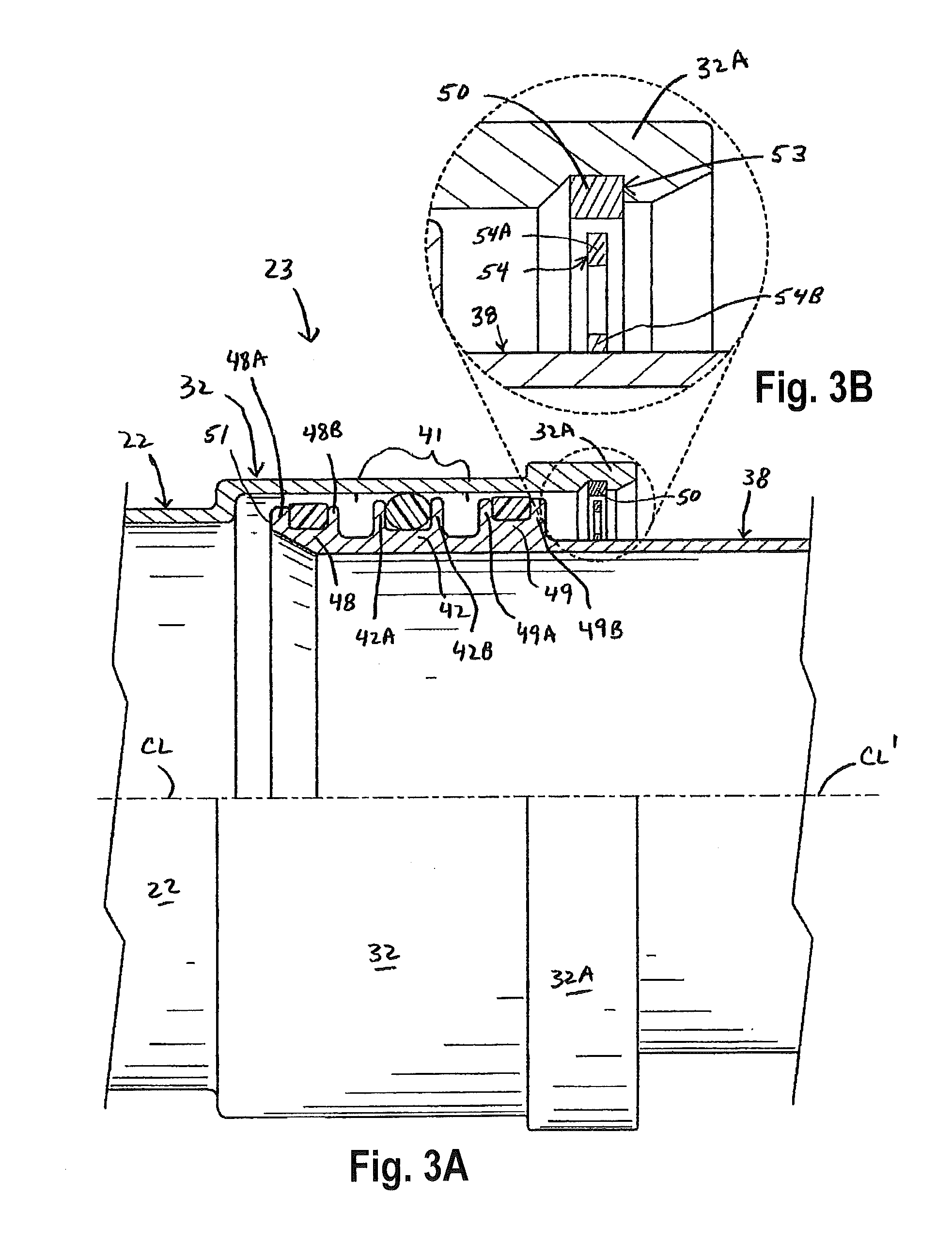
[0016]Referring now to the discussion that follows and also to the drawings, illustrative approaches to the disclosed systems and methods are shown in detail. Although the drawings represent some possible approaches, the drawings are not necessarily to scale and certain features may be exaggerated, removed, or partially sectioned to better illustrate and explain the present disclosure. Further, the descriptions set forth herein are not intended to be exhaustive or otherwise limit or restrict the claims to the precise forms and configurations shown in the drawings and disclosed in the following detailed description.

[0017]Moreover, a number of constants may be introduced in the discussion that follows. In some cases illustrative values of the constants are provided. In other cases, no specific values are given. The values of the constants will depend on characteristics of the associated hardware and the interrelationship of such characteristics with one another as well as environmenta...


PUM


Abstract

A compliant conduit connector system for the sealed joining of two fluid conduits having two or more slip bearings to maintain mechanical connection between the two fluid conduits and a sealing o-ring to maintain a fluid seal between the two fluid conduits is disclosed. A socket having an inner surface including a sealing surface is formed on an end of a first fluid conduit. A plurality of slip bearings are held in position on the outer surface of a second fluid conduit by respective bearing channels attached to an outer surface of the second fluid conduit where the slip bearings are in mechanical contact with an inner surface of the socket formed in the first fluid conduit. The o-Ring makes sealing contact with a sealing surface defined as part of the inner surface of the first fluid conduit. To assure electrical conductivity a conductor assembly contacts both the first fluid conduit and the second fluid conduit.

Description

TECHNICAL FIELD[0001]The compliant conduit connector system relates to a fluid coupling system for joining two fluid conduits or pipes such that the two conduits are sealed one to the other but are relatively free to move and deflect relative to one another while remaining in a sealed relationship.BACKGROUND ART[0002]Because of space confinements within an aircraft, there is difficulty in connecting two fluid conduits such as fuel lines within the aircraft structure. Thus, there is a need for a conduit connector system that is easy to install in confined areas. There is also a need to allow relative movement between the fluid conduits due to operational stresses imposed on the fuel system and aircraft structure. Known are ball type joints for connecting fluid conduits such as that disclosed in Mahoff U.S. Pat. No. 4,249,786 Compliant Coupling. In the type of joint disclosed in the Mahoff patent an o-ring is held in a channel formed on the outside surface of a first conduit and is po...

Claims


Application Information

Patent Timeline
Patent Type & Authority Patents(United States)
IPC IPC(8): F16L21/00
CPCF16L25/01F16L37/088F16L27/026
Inventor FLYNN, WILLIAM T.
Owner EATON INTELLIGENT POWER LTD
Why Eureka
Try Eureka