Thumb drive chassis structure

a thumb drive and chassis technology, applied in the direction of electrical apparatus casings/cabinets/drawers, coupling device connections, instruments, etc., can solve the problems of difficult handling and use, small sip memory devices that are difficult for people to carry, and can be customized in size but generally very small, so as to prevent upward restrict the movement of the assembly, and facilitate the manufacture.

Active Publication Date: 2013-01-29
KINGSTON DIGITAL CO LTD
View PDF8 Cites 7 Cited by
  • Summary
  • Abstract
  • Description
  • Claims
  • Application Information

AI Technical Summary

Benefits of technology

[0014]Another object of embodiments of the invention is to provide a thumb drive chassis structure and a method of manufacturing the same that hold a very small memory package, such as a “System-in-Package” or “SiP” memory device, and prevent pivoting at the mouth of the case and breaking the case when the USB connector is inserted into a USB port, and yet is inexpensive to manufacture.
[0019]The present invention discloses a USB thumb drive with a miniaturized memory storage assembly, such as a SiP memory device, that employs an extended chassis structure to support the miniaturized memory device within an ergonomically designed casing. The present invention discloses a miniaturized memory device secured within a USB connector housing, and further discloses an elongated platform chassis extending rearwardly from the back end of the USB housing. The elongated platform chassis forms a support structure, so that the USB connector housing and chassis can be supported within a thumb drive casing that is long and thick enough to be ergonomically compatible with a human hand and with portability. The USB housing and chassis structure prevents the USB housing from pivoting within mouth of the ergonomic casing when a user inserts the USB connector into the USB port of a laptop computer or similar machine.
[0020]The present invention also discloses a miniaturized memory storage assembly, such as a SiP memory device, that is simple to manufacture. The miniaturized memory storage assembly is inserted into a USB connector housing, preferably through a rear opening. The miniaturized memory storage assembly has a ramped, flexible latch projection extending from its side. The USB connector housing has a complimentary latch aperture in its side. The flexible, ramped latch projection is pushed inward when the miniaturized memory storage assembly is inserted into the USB connector housing. When the miniaturized memory storage assembly is fully inserted into the USB connector housing, the flexible latch snaps outward through the complimentary latch aperture and restricts movement of the assembly within the housing by preventing the assembly from being pulled back out as well as preventing upward movement of the assembly within the housing. A stop at the front of the USB connector housing prevents the miniaturized memory storage assembly from being pushed forward. The top surface of the USB connector housing also includes stamped apertures that form downwardly projecting tongues. These tongues push down against the top surface of the miniaturized memory storage assembly and further prevent movement of the assembly within the housing. The elongated platform chassis extending rearwardly from the USB connector housing snaps in place in an ergonomically designed thumb drive case. In one embodiment, the plastic case is formed of lower and upper halves. The elongated platform chassis snaps in place in the lower half of the case. Latches in the lower case snap into notches in the chassis. The upper half of the case is then fixed to the lower half by adhesive or friction welding.

Problems solved by technology

It is not so large that it is bulky, and it is not so small that it is hard to handle and use.
The size of these SiP devices could be customized but generally very small.
But, the small SiP memory devices can be awkward for a person to use and carry, because it is too small for easy handling by a human hand and it could be more easily lost than conventional thumb drives.
It is not easy to incorporate these miniaturized SiP memory devices into a conventional thumb drive casing, because the conventional thumb drive casing cannot provide sufficient support to the SiP device to prevent it from pivoting at the mouth of the conventional plastic case, thereby breaking the case when the USB connector is inserted into a USB port.

Method used


Image

  • Thumb drive chassis structure
  • Thumb drive chassis structure
  • Thumb drive chassis structure

Examples


Embodiment Construction

[0033]Reference will now be made in detail to the preferred embodiments of the invention, examples of which are illustrated in the accompanying drawings.

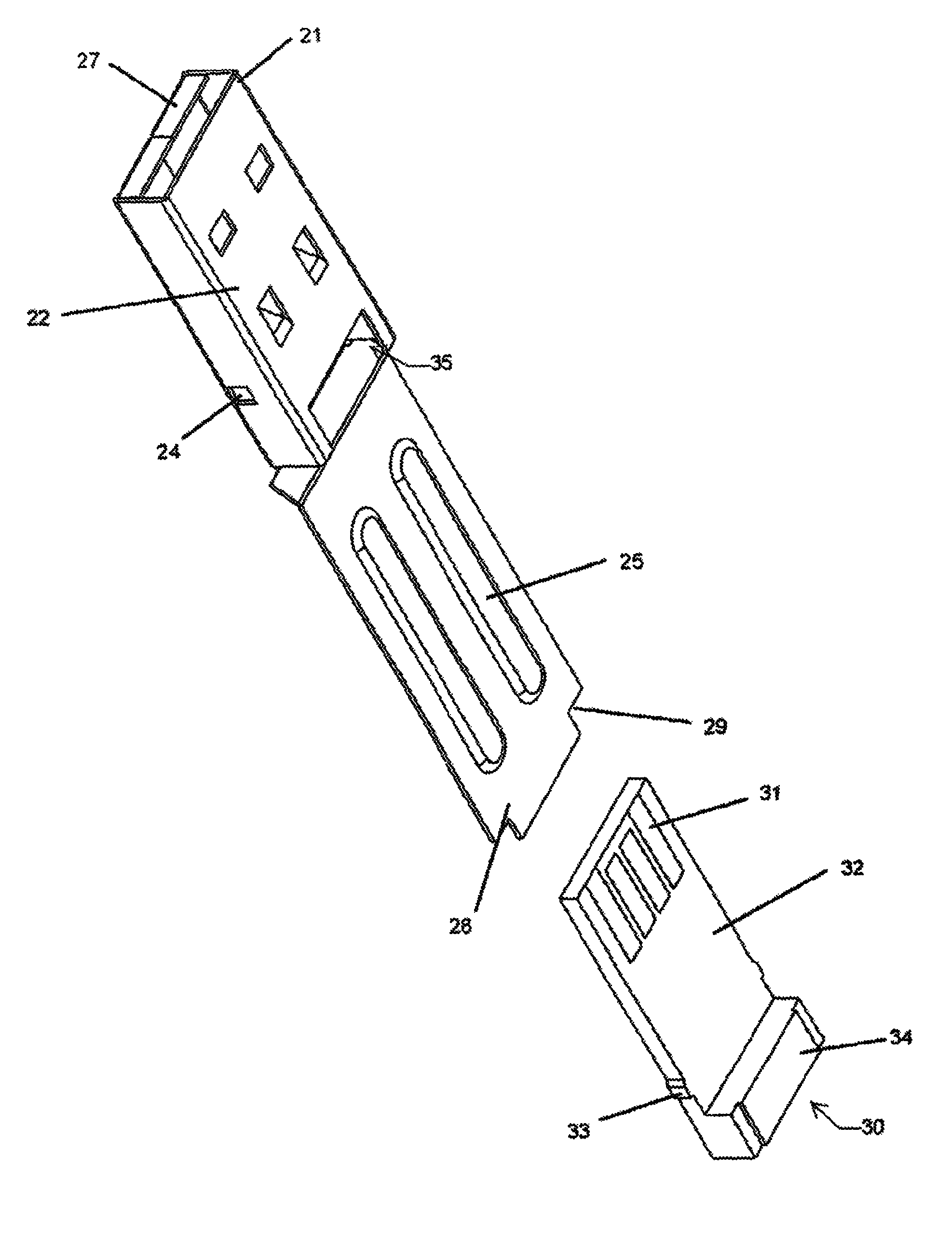
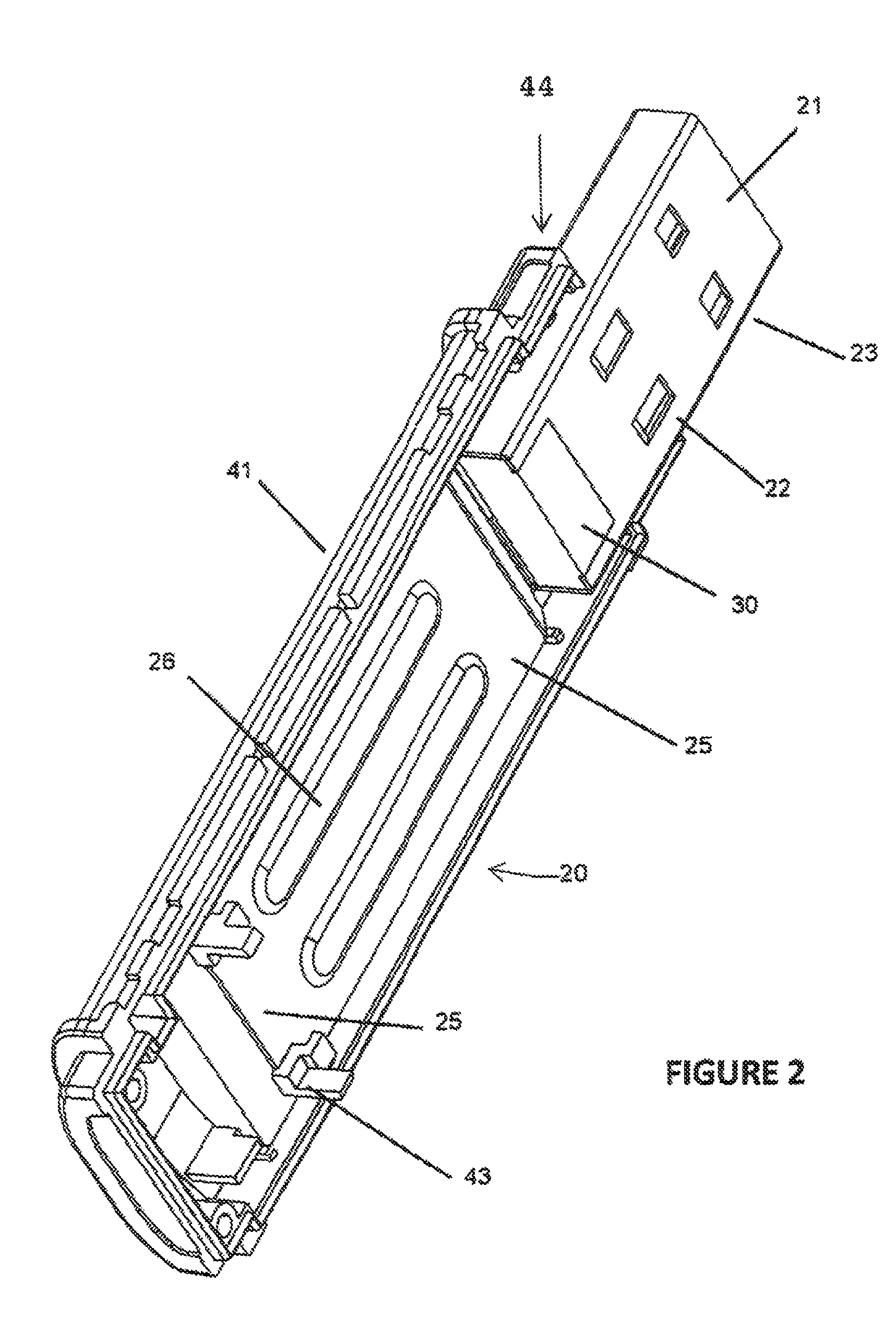
[0034]FIG. 2 is a perspective view of a thumb drive according to an embodiment of the present invention. In FIG. 2, a thumb drive 20 includes a lower casing half 41 and an upper casing half 42 (shown in FIG. 5). The lower and upper casing halves 41 and 42 when assembled together form a mouth 44 at one end. The lower casing half 41 supports a portion of a USB connector housing 22 at the mouth of the casing 44, and supports a platform chassis extension 25 extending rearwardly from the USB connector housing 22.

[0035]The lower casing half 41 includes stop structures 43 at the rear portion of the lower casing half 41 to provide positive mechanical fixture to the platform chassis extension 25. Notches 29 (shown in FIG. 3) at the rear end 28 of the platform chassis extension 25 mate with the notches 29 in the lower casing half 41. Strength...


PUM


Abstract

A thumb drive with a miniaturized memory storage assembly package that employs an extended chassis structure to support the miniaturized memory device within an ergonomically designed casing that is also simple to manufacture. The miniaturized memory storage assembly has a flexible latch projection extending from its side that mates with a complimentary latch aperture in the side of the connector housing. Downwardly projecting tongues in the top surface of the connector housing also prevent movement of the assembly within the housing. The elongated platform chassis extending rearwardly from the USB connector housing snaps in place in an ergonomically designed thumb drive case.

Description

[0001]The present invention claims priority to provisional application No. 61 / 397,173 filed on Jun. 7, 2010 which is incorporated in its entirety by reference.BACKGROUND OF THE INVENTION[0002]1. Field of the Invention[0003]The present invention relates generally to portable memory devices and, more specifically, to a USB thumb drive chassis adapted to support a System-in-Package (“SiP”), miniaturized flash drive configured to mate with an ergonomically-sized housing. The invention also discloses a method of manufacturing the same.[0004]2. Discussion of the Related Art[0005]Portable memory storage devices, such as memory devices with USB connectors, are increasingly utilized to portably transfer electronic data. One type of the portable memory storage devices are commonly referred to as thumb drives, which have ergonomically-sized housing that could be easily handled in a user's hand.[0006]FIG. 1A is a perspective view of a conventional thumb drive, and FIG. 1B is another perspective...

Claims


Application Information

Patent Timeline
Patent Type & Authority Patents(United States)
IPC IPC(8): H01R13/00
CPCH05K5/0278H01R13/6658
Inventor CHOU, PETER LEE KUOTARN, SHING KUOHO, JOHN PEI
Owner KINGSTON DIGITAL CO LTD
Why Eureka
Try Eureka