
Method and apparatus for detecting received signal in wireless communication system

a wireless communication system and received signal technology, applied in the direction of pulse technique, amplitude demodulation, transmission monitoring, etc., can solve the problems of inability to detect a wireless signal in which a frequency offset exists, high complexity of calculation, and increase in calculation amount, so as to reduce the complexity of calculation

Inactive Publication Date: 2013-01-29
ELECTRONICS & TELECOMM RES INST
View PDF6 Cites 0 Cited by
  • Summary
  • Abstract
  • Description
  • Claims
  • Application Information

AI Technical Summary

Benefits of technology

This approach reduces the complexity and amount of calculation required for signal detection while effectively detecting signals in wireless channels with frequency offsets, improving detection accuracy and efficiency.

Problems solved by technology

Therefore, the complexity of calculation is high.
Therefore, the amount of calculation inevitably increases.
Therefore, when the Goertzel algorithm is applied to a wireless communication system, that is, a wireless channel environment, it is impossible to detect a wireless signal in which a frequency offset exists.

Method used


Image

  • Method and apparatus for detecting received signal in wireless communication system
  • Method and apparatus for detecting received signal in wireless communication system
  • Method and apparatus for detecting received signal in wireless communication system

Examples


Embodiment Construction

[0018]Exemplary embodiments of the present invention will be described below in more detail with reference to the accompanying drawings. The present invention may, however, be embodied in different forms and should not be constructed as limited to the embodiments set forth herein. Rather, these embodiments are provided so that this disclosure will be thorough and complete, and will fully convey the scope of the present invention to those skilled in the art. Throughout the disclosure, like reference numerals refer to like parts throughout the various figures and embodiments of the present invention.

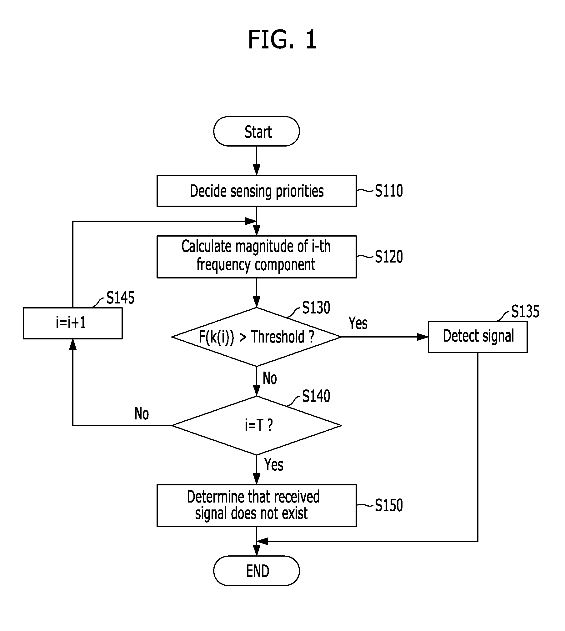
[0019]FIG. 1 is a flow chart explaining a method for detecting a received signal in accordance with an embodiment of the present invention. The received signal includes a signal which is received through a sensing receiver. To implement the method for detecting a received signal in accordance with the embodiment of the present invention, it is necessary to previously know the Rx band and c...


PUM


Abstract

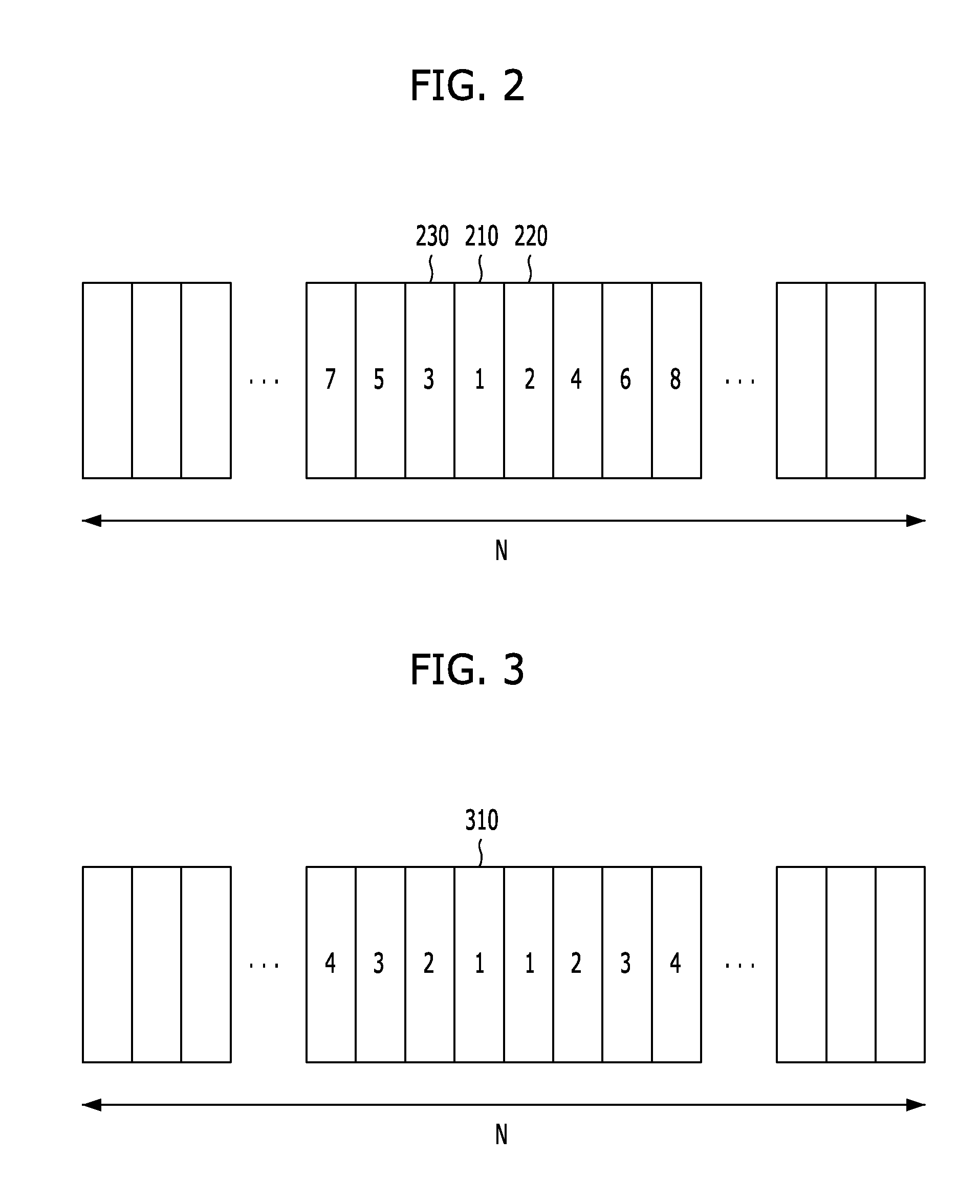
A method for detecting a received signal includes: dividing the entire band of the received signal into N frequency components where N is a natural number larger than one, and deciding a reference frequency component containing a reference frequency as a first priority sensing band among the N frequency components; deciding the sensing priorities of the other (N−1) frequency components in such a manner that the sensing priorities spread in both directions from the first priority sensing band; calculating the magnitude of each of the N frequency components in accordance with the decided sensing priorities; comparing the calculated magnitude of the frequency component with a predetermined threshold value; and when the calculated magnitude of the frequency component is larger than the threshold value, determining that the received signal exists.

Description

CROSS-REFERENCE(S) TO RELATED APPLICATIONS[0001]The present application claims priority of Korean Patent Application No. 10-2009-0117391, filed on Nov. 30, 2009, which is incorporated herein by reference in its entirety.BACKGROUND OF THE INVENTION[0002]1. Field of the Invention[0003]Exemplary embodiments of the present invention relate to a method and apparatus for detecting a received signal; and, more particularly, to a method and apparatus for detecting a received signal in a wireless communication system.[0004]2. Description of Related Art[0005]In the spectrum sensing of a wireless communication system, a signal received by a sensing receiver is detected as follows. First, the spectrum components of the entire bands of the received signal are calculated. Then, the calculated spectrum components are used to determine whether the received signal exists or not. In this case, a fast Fourier transform (FFT) algorithm for calculating the entire frequency bands at one time is mainly us...

Claims


Application Information

Patent Timeline
Patent Type & Authority Patents(United States)
IPC IPC(8): H04K1/10
CPCH04L27/0006H04L27/144
Inventor JUNG, HOI-YOONLIM, SUN-MINKIM, SANG-WONSONG, MYUNG-SUN
Owner ELECTRONICS & TELECOMM RES INST
Learn More