Area light source device and liquid crystal display device

a light source device and liquid crystal display technology, applied in the direction of instrumentation, lighting and heating apparatus, planar/plate-like light guides, etc., can solve the problems of light leakage from the area, difficult assembly of backlights, and easy warping of light guide plates, so as to reduce light leakage, enhance light emission luminance, and more evenly emit light

Active Publication Date: 2013-02-05
ORMON CORP
View PDF14 Cites 7 Cited by
  • Summary
  • Abstract
  • Description
  • Claims
  • Application Information

AI Technical Summary

Benefits of technology

[0023]One or more embodiments of the invention provides an area light source device capable of more evenly emitting light by reducing the leakage of light in the vicinity of the light source, and capable of enhancing the light emission luminance by exiting light of narrower directional characteristics. One or more embodiments of the invention also provides a liquid crystal display device using the area light source device.

Problems solved by technology

However, if the thickness of the light guide plate is thinned, the light guide plate becomes thin like a sheet, and thus the light guide plate tends to easily warp.
If the light guide plate tends to easily warp, the assembly of the backlight becomes difficult and the light may leak from the area where the light guide plate warped.
In the liquid crystal display device disclosed in Japanese Unexamined Patent Publication No. 5-88174, the vicinity of the light source lights up brightly since the light easily leaks in the vicinity of the light source thereby causing luminance unevenness at the display surface, and the display surface becomes dark due to lowering of the usage efficiency of the light.
Thus, the vicinity of the light source 29 lights up brightly thereby causing luminance unevenness, and the entire display surface cannot evenly emit light even when such area light source device 22 is used.
Moreover, the display surface becomes dark since the light leaks in the vicinity of the light source 29 and the usage efficiency of the light lowers.

Method used


Image

  • Area light source device and liquid crystal display device
  • Area light source device and liquid crystal display device
  • Area light source device and liquid crystal display device

Examples


first embodiment

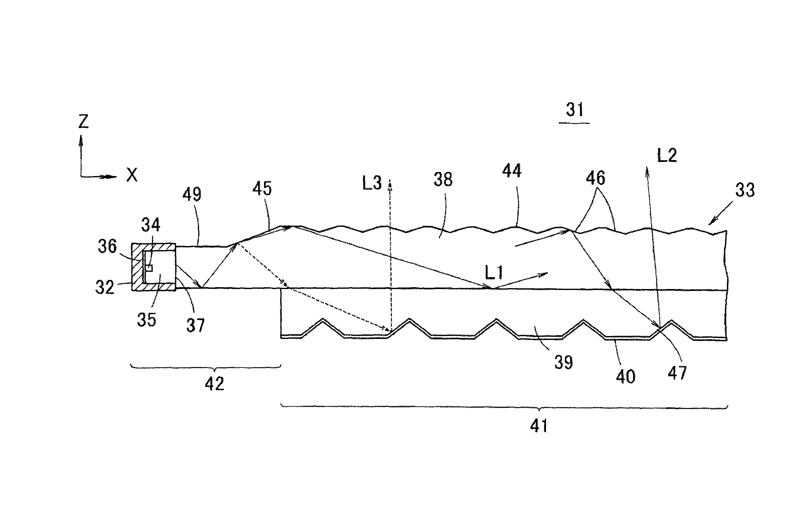
[0115]In the area light source device 51, the height of the light incident end face 43 is greater than in the first embodiment since the end of the light guide substrate 38 is the flat portion 54. Thus, the emitted light from the point light source 32 is less likely to leak to the outside of the light incident end face 43, and the usage efficiency (light collecting efficiency) of the light source enhances. However, the light reflected at the reverse tapered portion 53 easily leaks to the outside from the lower surface of the light introducing section 42 since the reverse tapered portion 53 exists adjacent to the flat portion 54.

[0116]Thus, a directivity conversion unit 55 as shown in FIG. 19 is provided at the back surface of the light introducing section 42 in the thin plate portion 49. The directivity conversion unit 55 is arranged in a rectangular region or a band-shaped region and is configured by radially lining V groove shaped directivity conversion patterns 48 of the same sha...

second embodiment

[0118]FIG. 23 shows the directional characteristics (directional characteristics seen from the Z direction) of the light exit from the light exit surface 44 in the area light source device 51 of the second embodiment, where it is apparent that a very narrow directional characteristic can be realized in the X-direction. According to the directional characteristics of FIG. 23, the ratio of the total light amount of the light exit in the direction within ±20° with respect to the total light amount of the light exit in the direction within ±90° with respect to the normal line of the light exit surface 44 is 98%, which shows a very narrow directional characteristic.

[0119]Thus, if the directivity conversion unit 55 is arranged so that the light totally reflected at the reverse tapered portion 53 is received by the directivity conversion unit 55, the directional characteristics of the light totally reflected at the reverse tapered portion 53 and reached to the lower surface of the light in...

fourth embodiment

[0127]FIG. 27 is a perspective view showing an area light source device 62 according to the present invention. In the area light source device 62, the tapered portion 45 is formed to an arcuate shape with the point light source 32 as substantially the center, and the region of semicircular shape surrounded by the tapered portion 45 is assumed as the thin plate portion 49. Effects similar to previous embodiments can be obtained in such mode as well.


PUM

PropertyMeasurementUnit
vertex angleaaaaaaaaaa
angleaaaaaaaaaa
angleaaaaaaaaaa

Abstract

An area light source device that is capable of more evenly emitting light and capable of enhancing the light emission luminance by exiting light of narrower directional characteristics. A light guide substrate includes a light introducing section and a light guide plate main body for exiting the light from a light exit surface. A number of diffusion patterns are formed at the light exit surface. A low refraction index layer is formed at the lower surface of the light guide plate main body, and a reflection layer is formed at the lower surface of the low refraction index layer. The point light source is arranged at a position facing the end face of the light introducing section. A tapered portion inclined to gradually increase the thickness of the light introducing section the farther away from the light source is arranged on the upper surface of the light introducing section.

Description

1. TECHNICAL FIELD[0001]The present invention relates to area light source devices and liquid crystal display devices, and specifically, to an area light source device capable of resolving the luminance unevenness at the light emitting surface and achieving narrow directivity of the exit light, and also capable of achieving evenness of the light emitting surface and higher luminance, and a liquid crystal display device using the area light source device.2. BACKGROUND[0002](Regarding Japanese Unexamined Patent Publication No. 5-88174) An additive sheet such as a light diffusion sheet needs to be omitted and the thickness of the entire light guide plate needs to be thinned in order to thin a backlight used in the liquid crystal display device, and the like.[0003]However, if the thickness of the light guide plate is thinned, the light guide plate becomes thin like a sheet, and thus the light guide plate tends to easily warp. If the light guide plate tends to easily warp, the assembly o...

Claims


Application Information

Patent Timeline
Patent Type & Authority Patents(United States)
IPC IPC(8): G02F1/1335
CPCG02B6/0016G02B6/002G02B6/0055G02B6/0038G02B6/0031
Inventor ISHIKAWA, TAKAKOTANOUE, YASUHIROSHINOHARA, MASAYUKIUENO, YOSHIHIRO
Owner ORMON CORP
Why Eureka
Try Eureka