Compressed air tool having silencer structure

a technology of silencer and compressed air, which is applied in the direction of portable power-driven tools, percussive tools, instruments, etc., can solve the problems of inefficient air motor drive, small holes between copper silencer copper particles, and non-smooth exhaust emission

Active Publication Date: 2016-07-05
STORM PNEUMATIC TOOL CO LTD
View PDF10 Cites 2 Cited by
  • Summary
  • Abstract
  • Description
  • Claims
  • Application Information

AI Technical Summary

Benefits of technology

[0007]A primary objective of the present disclosure is to provide a compressed air tool having a silencer structure for solving aforesaid problems, so that the exhaust can be emitted smoothly and the problem of air motor being driven inefficiently can be prevented.

Problems solved by technology

When the silencing cotton 93 is used as the silencing element, the oil included in the exhaust may jam the interstices of the silencing cotton 93 after the emitted exhaust is passed the silencing cotton 93 for a period of time, and it causes the problem of non-smooth exhaust emission, and such problem may make the air motor be driven inefficient.
The tiny holes between the copper particles of the copper silencer may be jammed by the oil included in the exhaust, so the aforesaid problem occurred in the silencing cotton may also happen in the copper silencer.

Method used


Image

  • Compressed air tool having silencer structure
  • Compressed air tool having silencer structure
  • Compressed air tool having silencer structure

Examples


Embodiment Construction

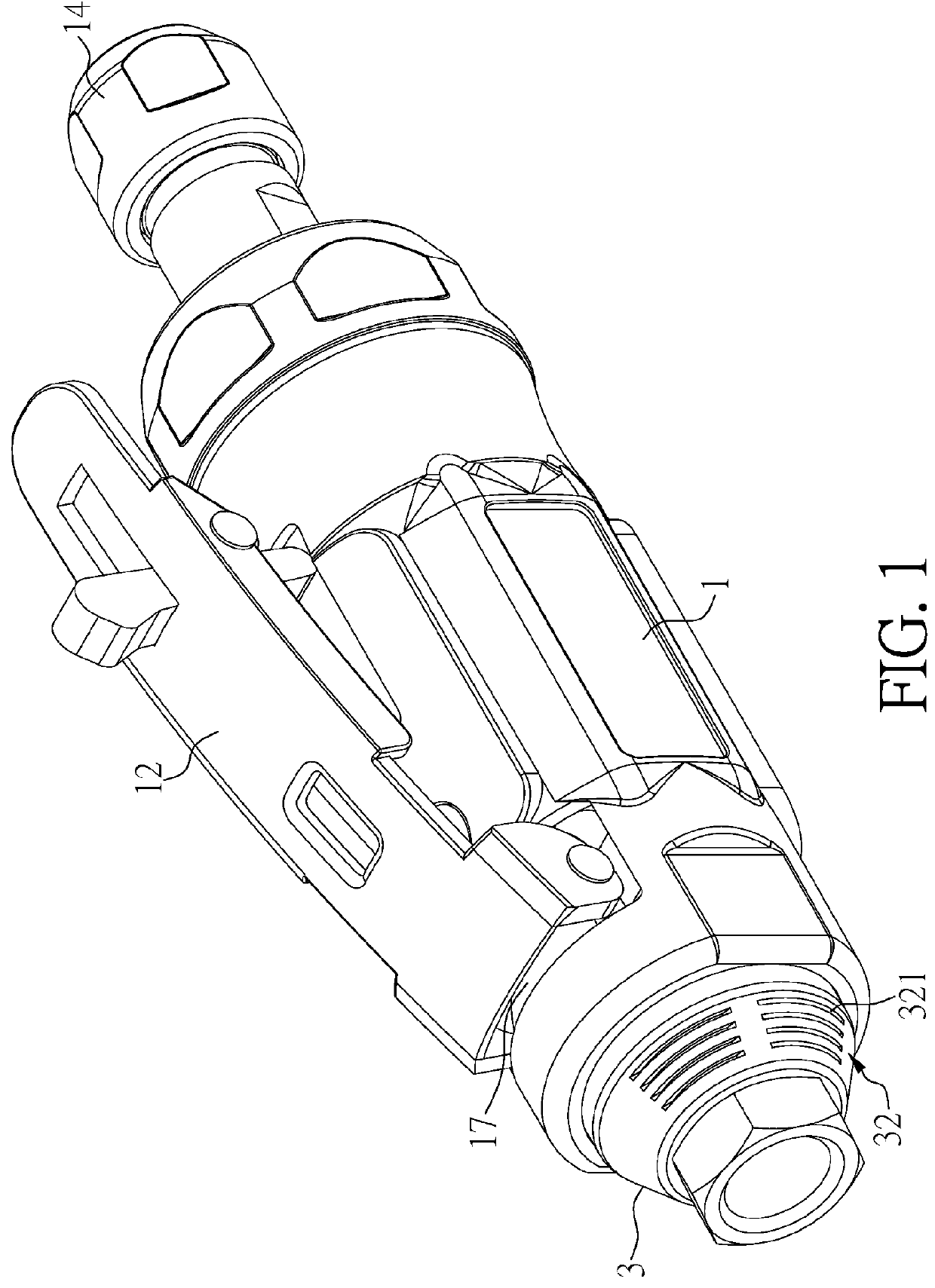
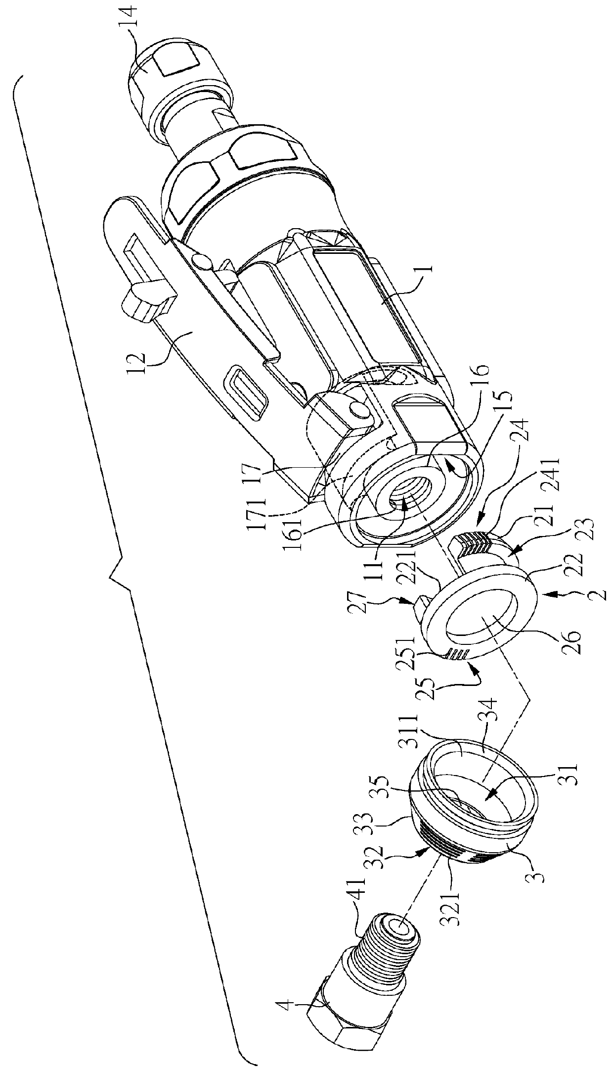
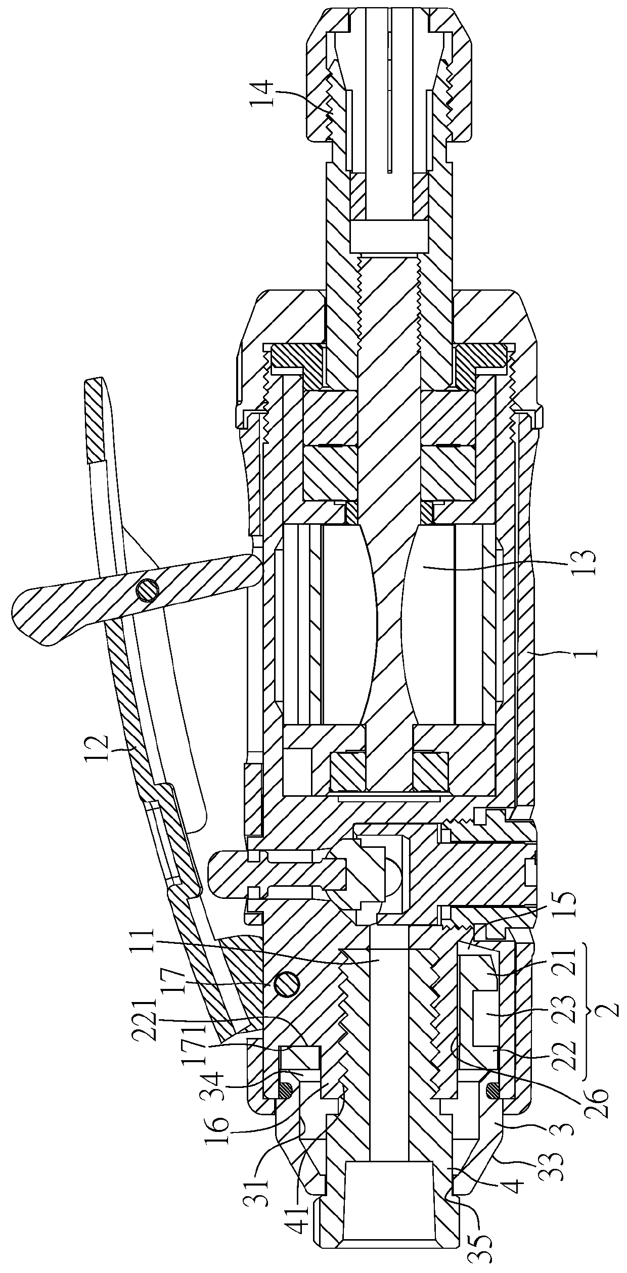
[0025]Reference will now be made in detail to the exemplary embodiments of the present disclosure, examples of which are illustrated in the accompanying drawings. Therefore, it is to be understood that the foregoing is illustrative of exemplary embodiments and is not to be construed as limited to the specific embodiments disclosed, and that modifications to the disclosed exemplary embodiments, as well as other exemplary embodiments, are intended to be included within the scope of the appended claims. These embodiments are provided so that this disclosure will be thorough and complete, and will fully convey the inventive concept to those skilled in the art. The relative proportions and ratios of elements in the drawings may be exaggerated or diminished in size for the sake of clarity and convenience in the drawings, and such arbitrary proportions are only illustrative and not limiting in any way. The same reference numbers are used in the drawings and the description to refer to the ...


PUM


Abstract

The present disclosure illustrates a compressed air tool having a silencer structure. A silencing element and an outer cover are disposed in an air exhaust channel of a main body of the compressed air tool. The silencing element has two walls and a channel. The two walls both have long slits, the long slits of the two walls are misaligned and not directly faced with each other. After the exhaust is inputted via the long slits of one of the two walls, the exhaust is flowed through the channel and emitted to the outside via the long slits of other of the two walls. Therefore, the air flow of the exhaust can be weakened, and the exhaust is then entered the countersink of the outer cover and emitted from the side hole, whereby the effect of silencing and reducing the noise caused by the emitted exhaust can be achieved.

Description

BACKGROUND OF THE INVENTION[0001]1. Field of the Invention[0002]The present disclosure relates to a compressed air tool, more particularly to a compressed air tool having a silencer structure.[0003]2. Description of the Related Art[0004]While being operated, the compressed air tool used in industrial field is usually connected to an gas source, and the high pressure gas is entered to drive an air motor via an inlet, such that a tool head of the compressed air tool starts to act, and the exhaust generated during operation of the air motor is emitted o the outsides via an air exhaust channel. In order to reduce the noise generated during the emission of the exhaust via the air exhaust channel, a silencer is usually disposed at the air exhaust channel. Main elements of the silencer for silencing includes silencing cotton made of cotton or non-woven fabric, or copper silencer which has numerous tiny holes formed by copper particles.[0005]As shown in FIG. 11, at a bottom of a handle 82 o...

Claims


Application Information

Patent Timeline
Patent Type & Authority Patents(United States)
IPC IPC(8): F01N1/08B25D9/00G10K11/00
CPCB25D9/00G10K11/002B25F5/00
Inventor SUN, YUNG YUNG
Owner STORM PNEUMATIC TOOL CO LTD
Why Eureka
Try Eureka