Electronic relay

a technology of electronic relays and relays, applied in relays, electromagnetic relay details, electrical apparatus casings/cabinets/drawers, etc., can solve the problems of large mechanical relay size, generating operation noise, and generating noise in the product employing the relay, so as to reduce the area necessary for installing the electronic relay, increase the noise performance of the product, and reduce the effect of heat emission

Active Publication Date: 2015-05-05
KOREA ELECTRIC TERMINAL
View PDF8 Cites 2 Cited by
  • Summary
  • Abstract
  • Description
  • Claims
  • Application Information

AI Technical Summary

Benefits of technology

[0019]The electronic relay according to the present invention has the following effects.
[0020]That is, according to the electronic relay of the present invention, since a printed circuit board includes a switching function, operation noise is not generated at all, which significantly increases noise performance of a product employing the electronic relay.
[0021]According to the present invention, since one side of a housing is opened and one surface of the printed circuit board is exposed to the outside of the housing, heat can be more smoothly emitted from an interior of the housing to the outside. Thus, operation reliability of the printed circuit board in the housing can be constantly maintained.
[0022]Further, according to the present invention, since the printed circuit board is not installed in a transverse direction of the housing but is erected to form one outer surface of the housing, the electronic relay can be designed such that an area of a lower surface of the electronic relay does not depend on the printed circuit board. Thus, since an area of the lower surface of the housing is minimized, an area necessary for installing the electronic relay can be minimized.
[0023]Furthermore, according to the present invention, since the printed circuit board, the terminal plate, the terminal, and the lower cover to be installed within the housing are assembled in the housing while they form one assembly, assembling performance is excellent. In particular, since a plurality of terminals is assembled in the housing while being fixed between the terminal plate and the lower cover, the terminals can be more easily assembled.
[0024]In addition, according to the present invention, a fixing resin is injected into a space between the printed circuit board and the lower cover so that the printed circuit board, the lower cover, the terminal plate, and the terminals are coupled to each other, water cannot be penetrate into the interior of the housing and the components can be more firmly coupled.

Problems solved by technology

In the mechanical relay, since a coil should be wound on a core and a space for moving the moving iron and a large installation space for a spring for returning the iron are necessary, the size of the mechanical relay becomes large.
Further, operation noise is generated while the moving iron is moved, generating noise in a product employing the relay.
In addition, since the relay is large as compared with other components such as a fuse, the size of the product employing the relay becomes large.

Method used


Image

  • Electronic relay
  • Electronic relay
  • Electronic relay

Examples


Embodiment Construction

Technical Problem

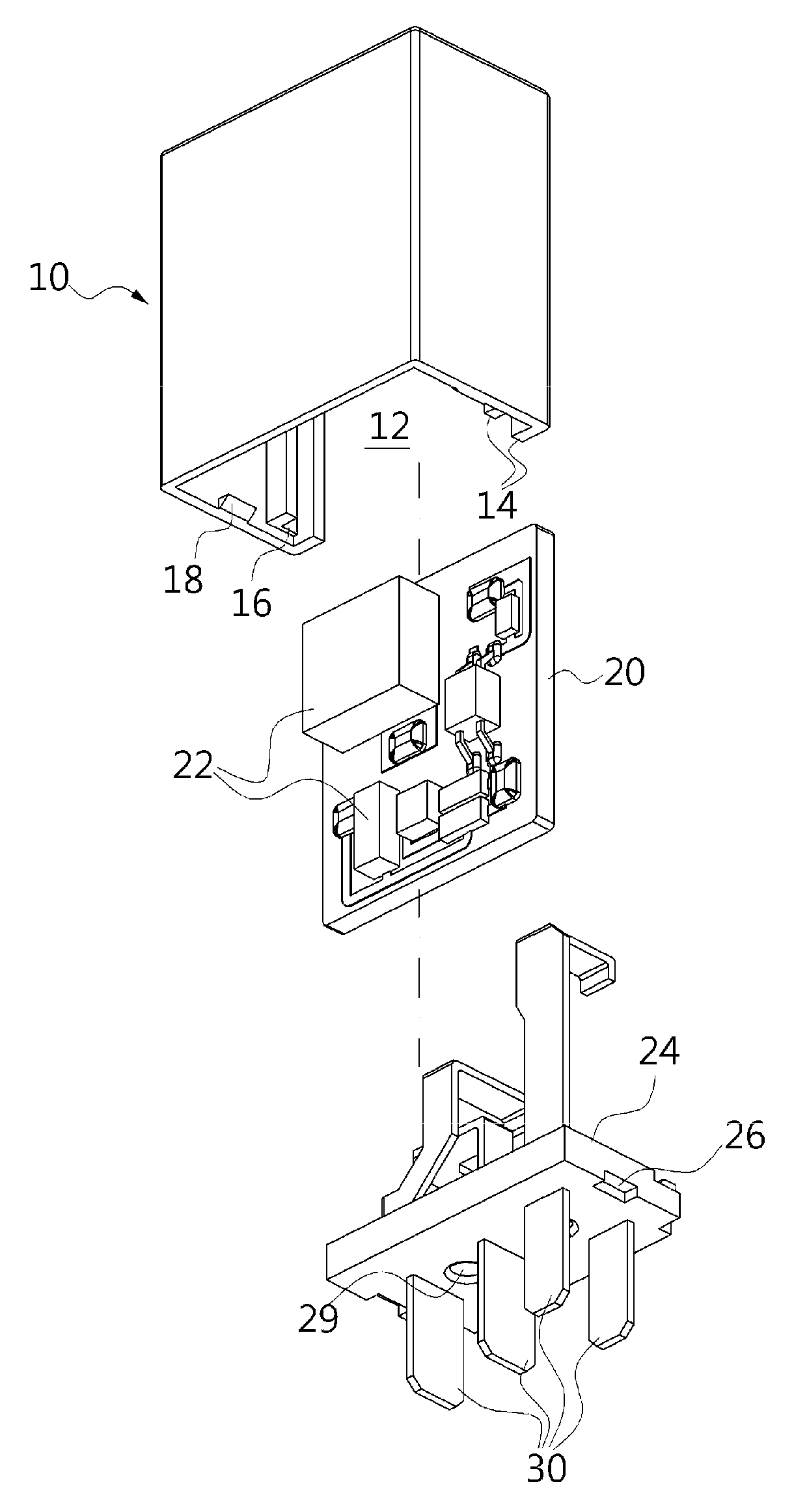
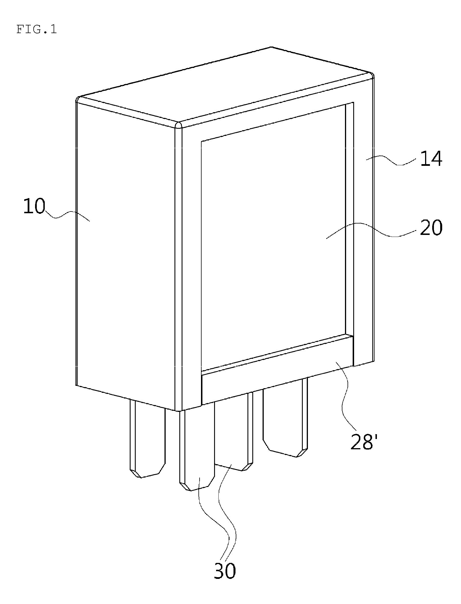
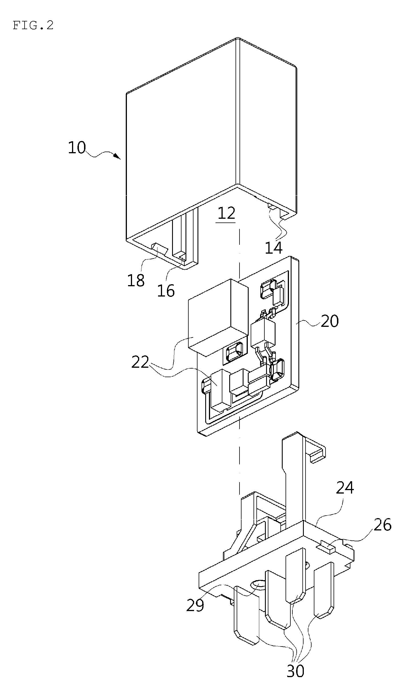
[0008]Therefore, the present invention has been made in view of the above-mentioned problems, and an aspect of the present invention is to provide an electronic relay which uses a printed circuit board having a switching function.

[0009]Another aspect of the present invention is to more smoothly emit heat generated by an electronic relay using a printed circuit board having a switching function to the outside.

[0010]Another object of the present invention is to provide an electronic relay which requires a minimum installation area.

[0011]Another object of the present invention is to provide an electronic relay which can be more easily assembled.

[0012]Another object of the present invention is to provide an electronic relay whose parts are more firmly coupled and which shows excellent waterproof performance.

[0013]Another object of the present invention is to transfer a fixing resin supplied to one side of a printed circuit board installed within a housing to a periphery...


PUM


Abstract

An electronic relay includes: a housing having an interior space therein and a lateral side and a lower side of which are opened, a board installation part being formed along a periphery of the opened side of the housing; a printed circuit board a periphery of which is inserted into and installed in the board installation part of the housing, for shielding the opened side of the housing and performing a switching function; a lower cover for shielding a lower side of the housing, one side edge of the printed circuit board being fixed to the lower cover; and terminals ends of which are electrically connected to the printed circuit board and opposite ends of which pass through the lower cover to protrude to the outside.

Description

CROSS REFERENCE TO PRIOR APPLICATION[0001]This application is a National Stage Patent Application of PCT International Patent Application No. PCT / KR2011 / 004160 (filed on Jun. 7, 2011) under 35 U.S.C. §371, which claims priority to Korean Patent Application Nos. 10-2010-0080541 (filed on Aug. 19, 2010), 10-2010-0080542 (filed on Aug. 19, 2010) and 10-2010-0132152 (filed on Dec. 22, 2010) which are all hereby incorporated by reference in their entirety.TECHNICAL FIELD[0002]The present invention relates to an electronic relay, and more particularly to an electronic relay which employs a printed circuit board having a function of interrupting flow of a current to be operated in an electronic manner.BACKGROUND ART[0003]A relay refers to a type of switch, and controls a higher voltage and a current with a low DC voltage. According to the related art, relays use a principle of an electromagnet. That is, if a coil is wound on a core and current flows through the coil, they act as an electro...

Claims


Application Information

Patent Timeline
Patent Type & Authority Patents(United States)
IPC IPC(8): H01H85/20H02B1/18H01H50/02H05K5/00
CPCH01H50/021H05K5/0039
Inventor LEE, JONG-MINKIM, GIL-SUJANG, CHUL-JIN
Owner KOREA ELECTRIC TERMINAL
Why Eureka
Try Eureka