Plasma monitoring device and method

a monitoring device and plasma technology, applied in plasma techniques, television systems, instruments, etc., can solve problems such as difficult implementation, environmental protection, and troublesome cleaning of micro-circuits

Inactive Publication Date: 2010-06-17
SNU PRECISION CO LTD
View PDF24 Cites 2 Cited by
  • Summary
  • Abstract
  • Description
  • Claims
  • Application Information

AI Technical Summary

Benefits of technology

[0029]The plasma monitoring device according to the present invention is advantageous in that, by obtaining an image of the plasma emission state and analyzing pixel information of the image by the controller, the plasma emission state can be monitored in real time.
[0030]According to the result of analysis by the controller, the plasma discharge condition is adjusted to control the amount of generated plasma. The amount of reaction gas supplied to the plasma supply means is also adjusted to control the amount of generated plasma.
[0031]The device has a number of camera units arranged at a predetermined distance from each other to monitor the plasma emission state throughout the entire area. This guarantees that, even if the amount of emitted plasma fluctuates in a specific area, the fluctuation can be spotted. The amount of generated plasma is controlled based on this so that plasma can be evenly emitted through the entire area of the object.
[0032]The device has plasma supply means arranged to supply plasma to the top and bottom surfaces of the object, respectively, and camera units positioned opposite respective plasma supply means so that both surfaces of the object can be treated simultaneously.

Problems solved by technology

Conventional wet cleaning methods using liquid chemicals have the advantages of easy processing and inexpensiveness, but have trouble in cleaning micro circuits.
In addition, the use of chemicals is not environmentally-friendly.
This necessitates dry cleaning equipment using plasma, which can clean micro circuits, although the technical implementation is not easy.
Despite excellent cleaning performance, this type of method is not widely used because the fact that a vacuum device is needed to maintain low pressure makes its application to continuous processes difficult.
However, this type of plasma monitoring based on photodiodes has a problem in that it can only determine whether plasma is being emitted or not.
In other words, this approach cannot measure the amount of emitted plasma throughout the entire area.
As a result, the substrate may not be cleaned evenly if plasma is supplied irregularly.

Method used


Image

  • Plasma monitoring device and method
  • Plasma monitoring device and method
  • Plasma monitoring device and method

Examples


Embodiment Construction

[0039]Hereinafter, exemplary embodiments of the present invention will be described with reference to the accompanying drawings.

MODE FOR THE INVENTION

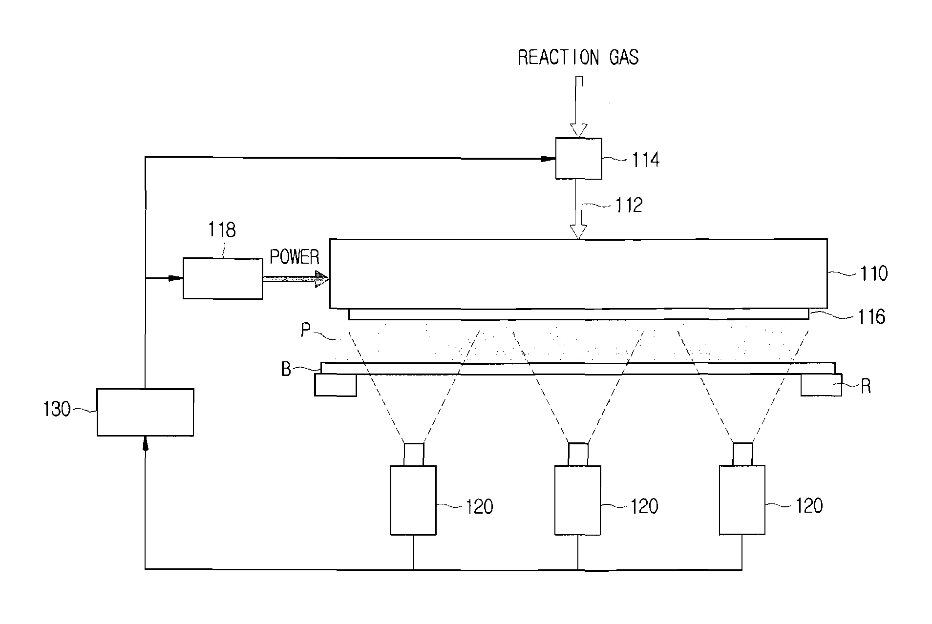
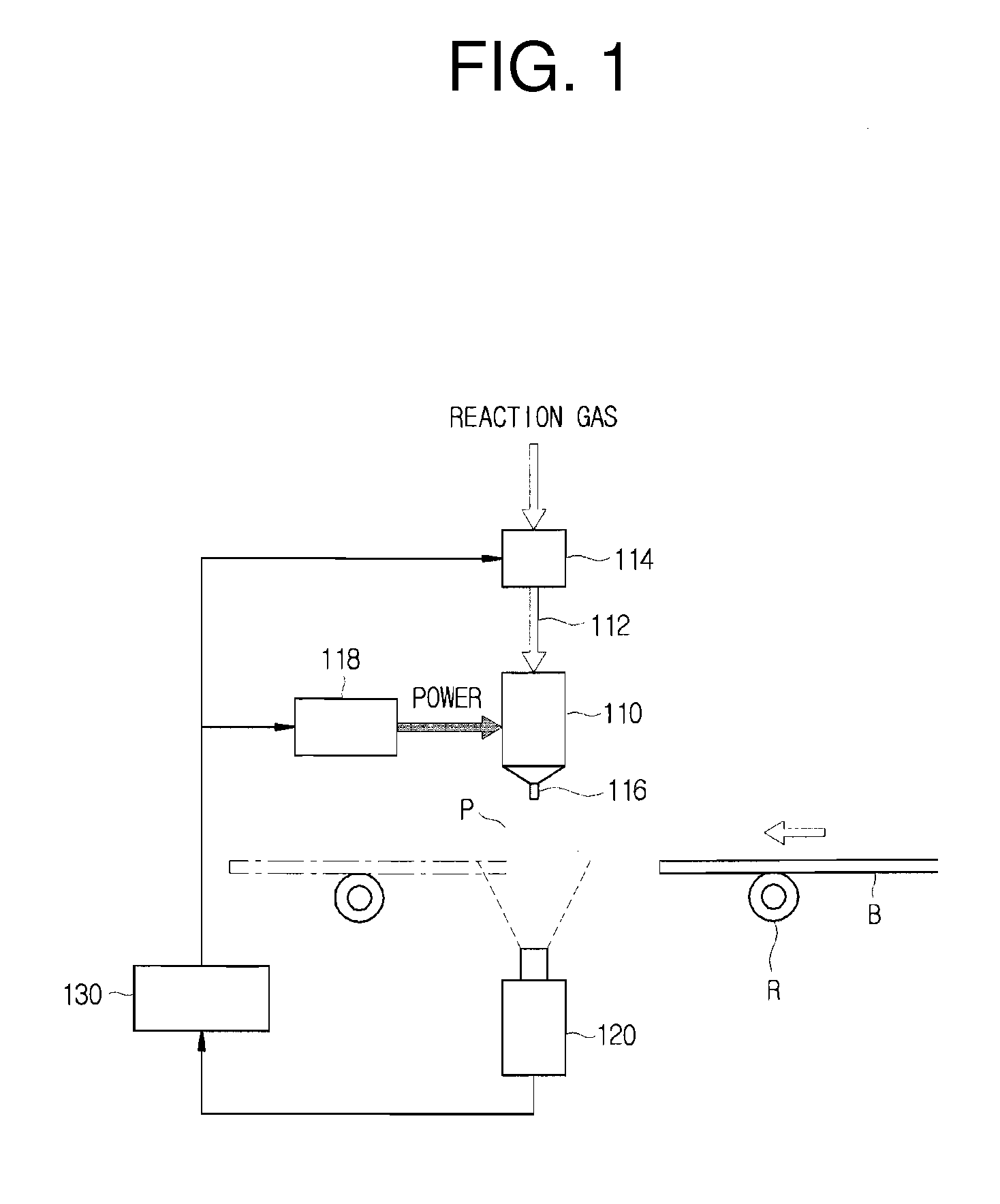
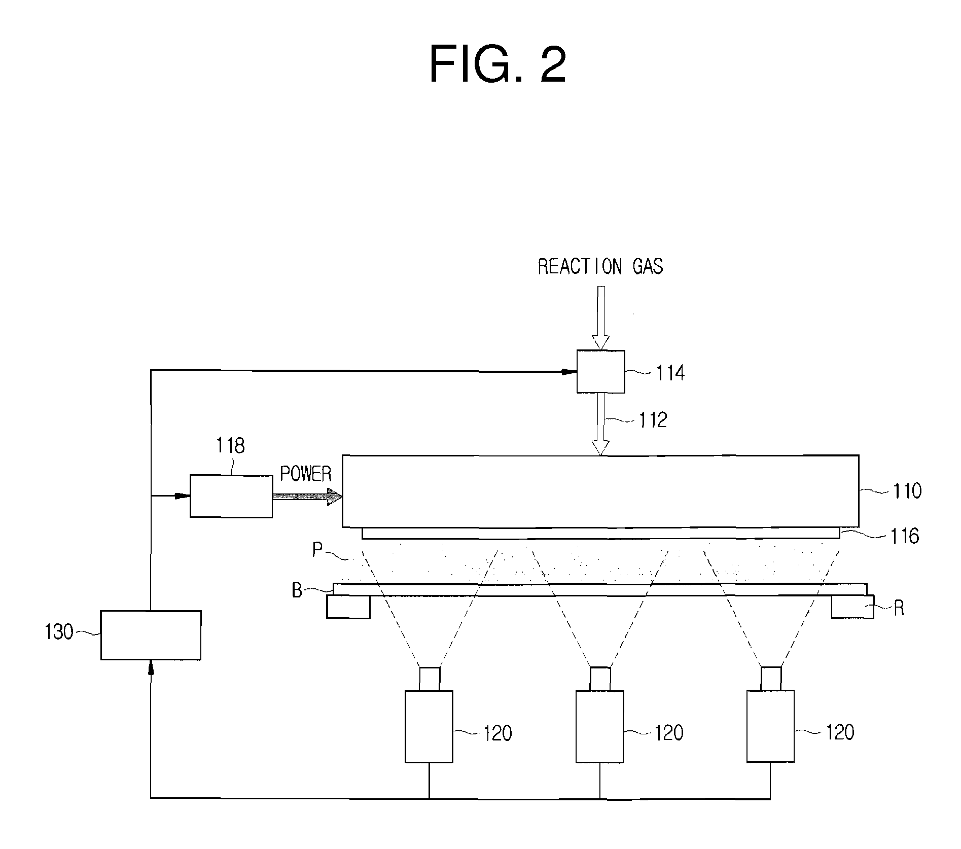
[0040]FIG. 1 is a front sectional view of a plasma monitoring device according to the present invention, and FIG. 2 is a lateral sectional view of a plasma monitoring device according to the present invention.

[0041]As shown in the drawings, the plasma monitoring device according to the present invention is applied to a device for plasma cleaning, plasma ashing, or plasma etching, and includes a plasma supply means 110 for emitting plasma P toward an object B, camera units 120 positioned toward the plasma supply means 110, and a controller 130 for analyzing images obtained by the camera units 120.

[0042]The plasma supply means 110 receives power and ionizes a reaction gas contained therein to generate plasma. The plasma supply means 110 includes a supply line 112 for supplying a reaction gas, an adjustment means 114 formed on the supply...


PUM


Abstract

A plasma monitoring device includes a plasma supplier including a power supply, a reaction gas supply line, and an emission nozzle for emitting plasma, which is generated therein, toward an object; a camera unit for obtaining an image of the plasma emission state; and a controller for obtaining a measurement value by converting pixel information of the image into a numerical value and comparing it with a reference value, which is a measurement value in a normal emission state, to check the plasma emission state. The camera unit obtains an image of the plasma emission state, and the controller analyzes the image to obtain a measurement value, which is used to monitor the state of plasma in real time and control the amount of reaction gas supplied to the plasma supplier and the plasma discharge condition, so that plasma is evenly emitted from the plasma supplier.

Description

TECHNICAL FIELD [0001]The present invention relates to a plasma monitoring device for obtaining an image of the plasma emission state so that the amount of emitted plasma is adjusted according to a measurement value obtained from analysis of the image.BACKGROUND ART [0002]In general, methods for treating the surface of a substrate, including removal of contaminants (e.g. organic substances) from the surface of the substrate, removal of resist, attachment of organic film, surface deformation, improved film formation, reduction of a metal oxide, and cleaning of a glass substrate for liquid crystals, are classified into wet cleaning methods using chemicals and dry cleaning methods using plasma.[0003]Conventional wet cleaning methods using liquid chemicals have the advantages of easy processing and inexpensiveness, but have trouble in cleaning micro circuits. In addition, the use of chemicals is not environmentally-friendly.[0004]This necessitates dry cleaning equipment using plasma, wh...

Claims


Application Information

Patent Timeline
Patent Type & Authority Applications(United States)
IPC IPC(8): H04N7/18H05H1/00
CPCH01J37/32357H05H1/0025H01J37/32935H01J37/32825H01L21/3065
Inventor SHIN, HEUNG HYUNAHN, WOO JUNG
Owner SNU PRECISION CO LTD
Why Eureka
Try Eureka