Backlight module and liquid crystal display using the same

a backlight module and liquid crystal display technology, applied in lighting and heating apparatus, lighting device details, instruments, etc., can solve the problems of raising and the cost of the reflecting layer also rising the cost of the lcd panel

Active Publication Date: 2014-08-26
TCL CHINA STAR OPTOELECTRONICS TECH CO LTD
View PDF15 Cites 2 Cited by
  • Summary
  • Abstract
  • Description
  • Claims
  • Application Information

AI Technical Summary

Benefits of technology

[0018]In the present disclosure, the first micro-structure is disposed on the light emitting side of the light tube for breaking the total reflections of the light in the light tube and allowing the light to be emitted from the light tube evenly. Also, the reflecting structure is disposed on non-light emitting side for improving the using efficiency of the light and reducing the manufacturing cost of the backlight module. Additionally, the fluorescent layer is coated on the light emitting side for improving a color saturation level of a LCD using the backlight module.

Problems solved by technology

However, the heat dissipating structure raises the cost of the LCD.
However, the metal reflecting layer also raises the cost of the LCD panel.

Method used


Image

  • Backlight module and liquid crystal display using the same
  • Backlight module and liquid crystal display using the same
  • Backlight module and liquid crystal display using the same

Examples


Embodiment Construction

[0029]The disclosure is illustrated by way of example and not by way of limitation in the figures of the accompanying drawings in which like references indicate similar elements. It should be noted that references to “an” or “one” embodiment is this disclosure are not necessarily to the same embodiment, and such references mean at least one.

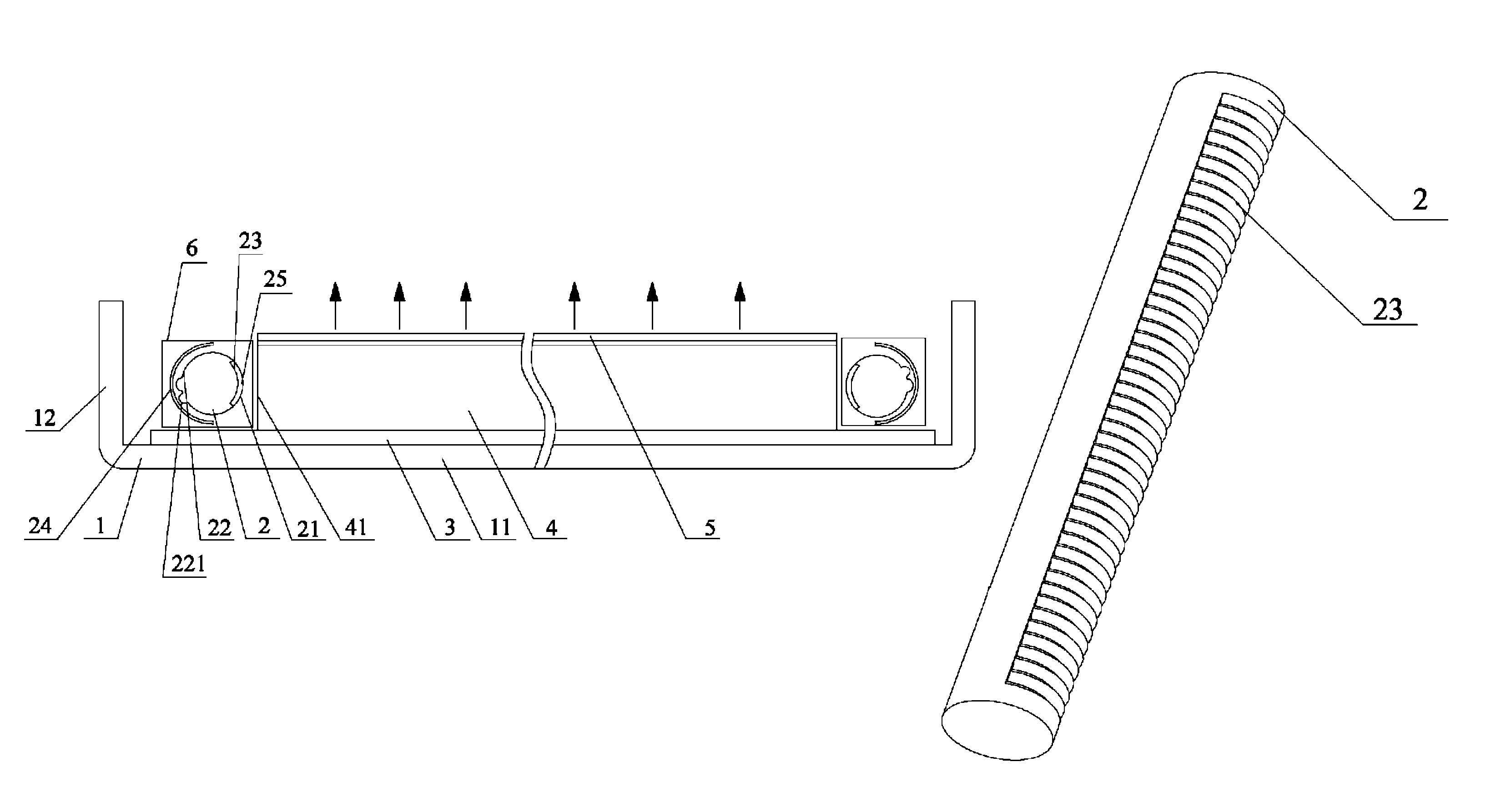
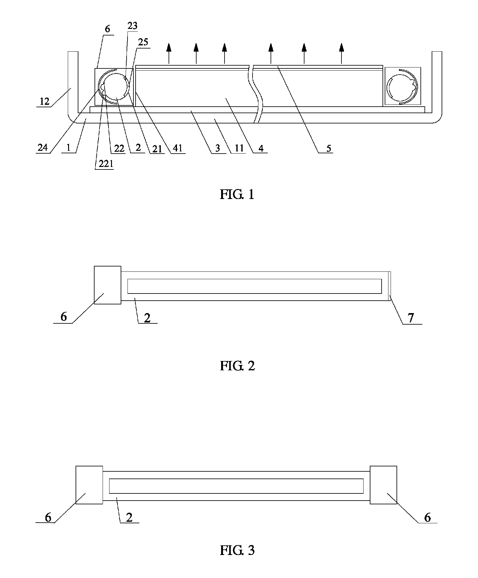
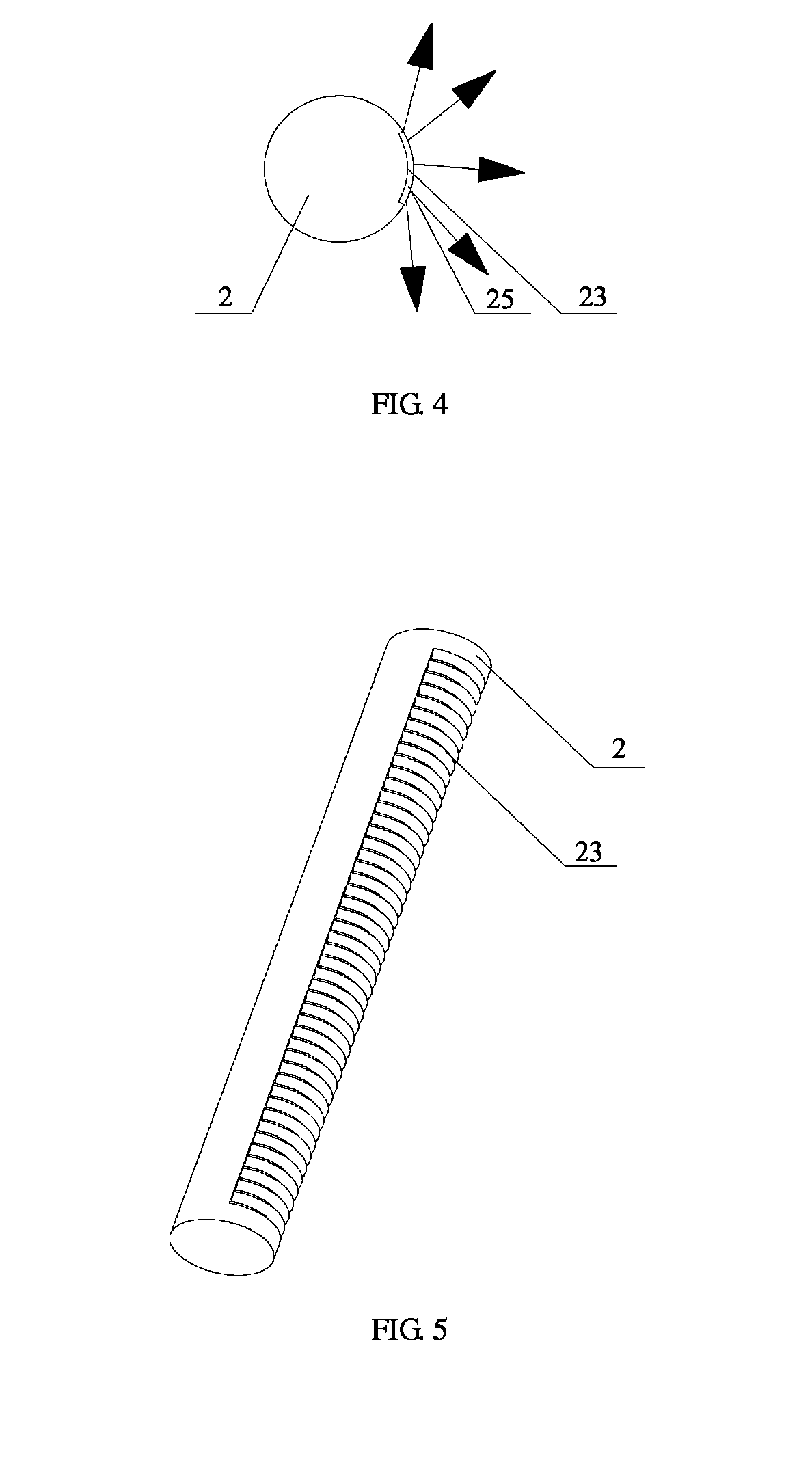
[0030]Referring to FIGS. 1 and 2, a backlight module according to a first embodiment of the present disclosure includes a back plate 1, two light tubes 2, a reflecting plate 3, a light guide plate 4, an optical film 5, and at least two light source coupling devices 6.

[0031]The back plate 1 includes a base portion 11 and two side portions 12 extending from two opposite ends of the base portion 11 respectively. The reflecting plate 3 is arranged on the base portion 11 and is located between the two side portions 12.

[0032]The light guide plate 4 is arranged on the reflecting plate 3. The light guide plate 4 includes a bottom surface corresponding to...


PUM


Abstract

The present disclosure provides a backlight module. The backlight module includes at least one light tube. Each light tube includes a light emitting side for emitting light and a first micro-structure disposed on the light emitting side for breaking total reflections of the light in the light tube. With the first micro-structure disposed on the light emitting side of the light tube, the total reflections of the light in the light tube can be broken to allow the light to be emitted from the light tube evenly. Also, the reflecting structure is disposed on non-light emitting side for improving the using efficiency of the light and reducing the manufacturing cost of the backlight module. Additionally, the fluorescent layer is coated on the light emitting side for improving a color saturation level of a LCD using the backlight module.

Description

BACKGROUND[0001]1. Technical Field[0002]The present disclosure relates to liquid crystal displaying technologies, and particularly, to a backlight module and a liquid crystal display using the same.[0003]2. Description of Related Art[0004]Cold cathode fluorescent lamps (CCFLs) or light emitting diodes (LEDs) matrix are often used in backlight modules of liquid crystal displays (LCDs) as a light source. As CCFL includes mercury, which is harmful to the environment, it is tend to be replaced by LED matrix. For the LED matrix, since it includes a number of LEDs, heat generated thereby is so much that the displaying effect of the LCD is influenced. Therefore, a heat dissipating structure is generally needed for LED matrix. However, the heat dissipating structure raises the cost of the LCD.[0005]In another aspect, to even light coming out from the light source and to improve the efficiency of the light source, a point light source is usually converted to a line light source. Specifically...

Claims


Application Information

Patent Timeline
Patent Type & Authority Patents(United States)
IPC IPC(8): F21V7/04
CPCG02B6/0028G02B6/0038G02B6/0068G02B6/0073G02F1/133605G02F1/133615G02F2001/133607G02F2001/133614G02F1/133607G02F1/133614
Inventor HSIAO, YU-CHUNYANG, RUILIAN
Owner TCL CHINA STAR OPTOELECTRONICS TECH CO LTD
Why Eureka
Try Eureka