
Composition for ceramics with carbon layer and manufactured method of ceramics using this

Inactive Publication Date: 2010-07-15
KIM KOO HAN
View PDF10 Cites 2 Cited by
  • Summary
  • Abstract
  • Description
  • Claims
  • Application Information

AI Technical Summary

Benefits of technology

[0029]The ceramic moulding with a carbon layer according to the present invention manufactured as described above has superior adiabatic property, high heat resistance and an effect of emitting far infrared ray evenly since it includes a carbonized carbon layer therein.

Problems solved by technology

However, such brick has shortcomings in that wood flour remains partially as a carbon body due to firing flames in firing process, or is burned out completely thereby forming a porous brick and thus damaging its appearance.
However, such method has shortcomings in that the operation becomes complex since different heat sources must be provided, and the indispensable use for expensive reducing flames (reducing flames at a specific temperature require more fuel cost and longer heating time relative to oxidizing flames) makes it uneconomical.
Furthermore, more attention is required to be paid to provision of oxidizing flames since if it takes a long time for providing oxidizing flames, even inner carbon bodies may be vaporized.

Method used


Image

  • Composition for ceramics with carbon layer and manufactured method of ceramics using this
  • Composition for ceramics with carbon layer and manufactured method of ceramics using this
  • Composition for ceramics with carbon layer and manufactured method of ceramics using this

Examples


example 1

[0035]A composition was mixed in a component ratio described in Table 1 below, and was formed into mouldings in brick form and plate form, and then the formed mouldings were fired with oxidizing flames in a kiln at 1200° C.

TABLE 1Carbon bodyWoodpowderElvanflour(ligniteCeramicMaterialLoessClaypowderSchamotte(saw dust)powder)WaterglazeWt %54152474112(Terra alba 0.8Limestone 0.8Ash 0.4)

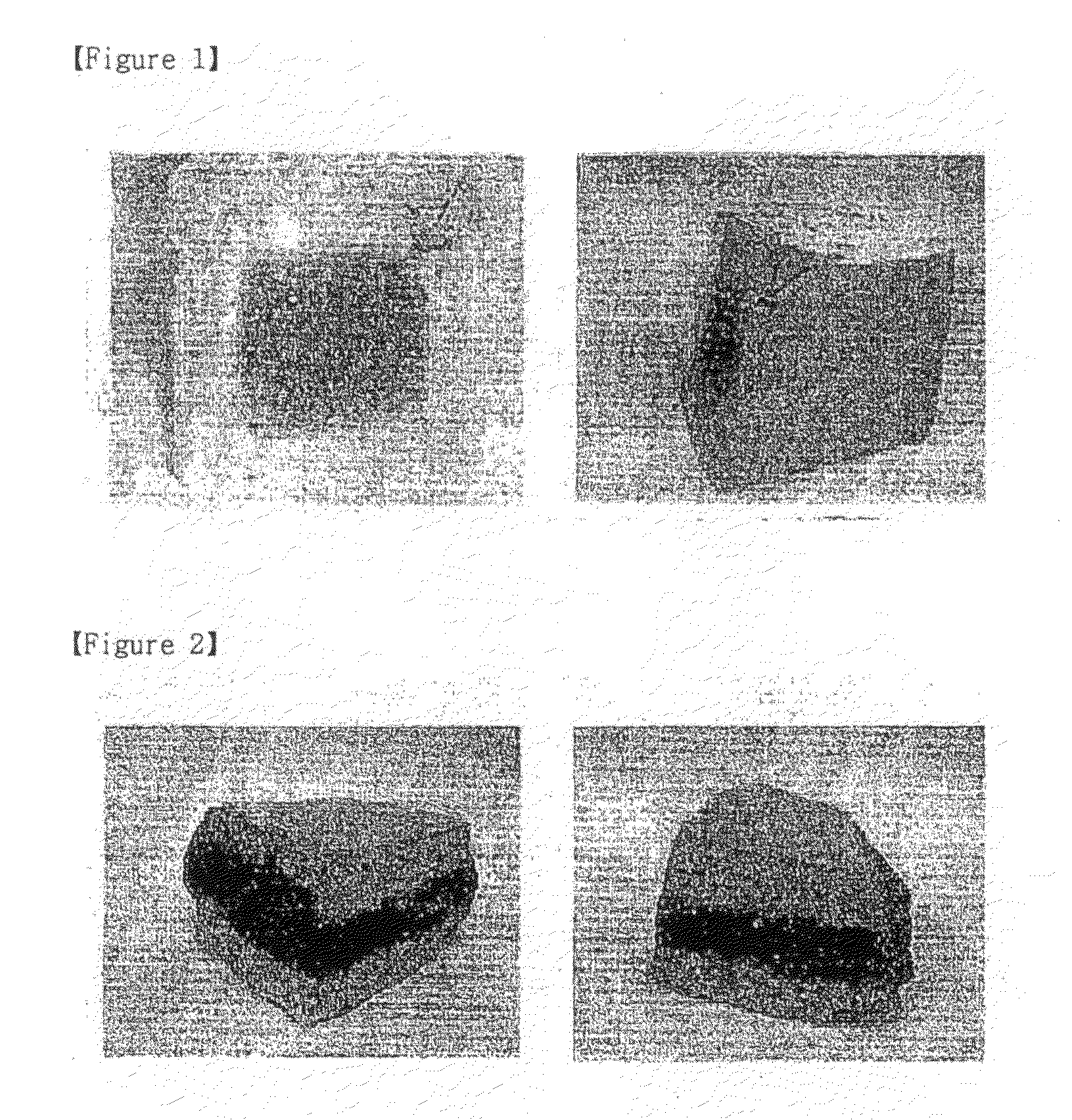
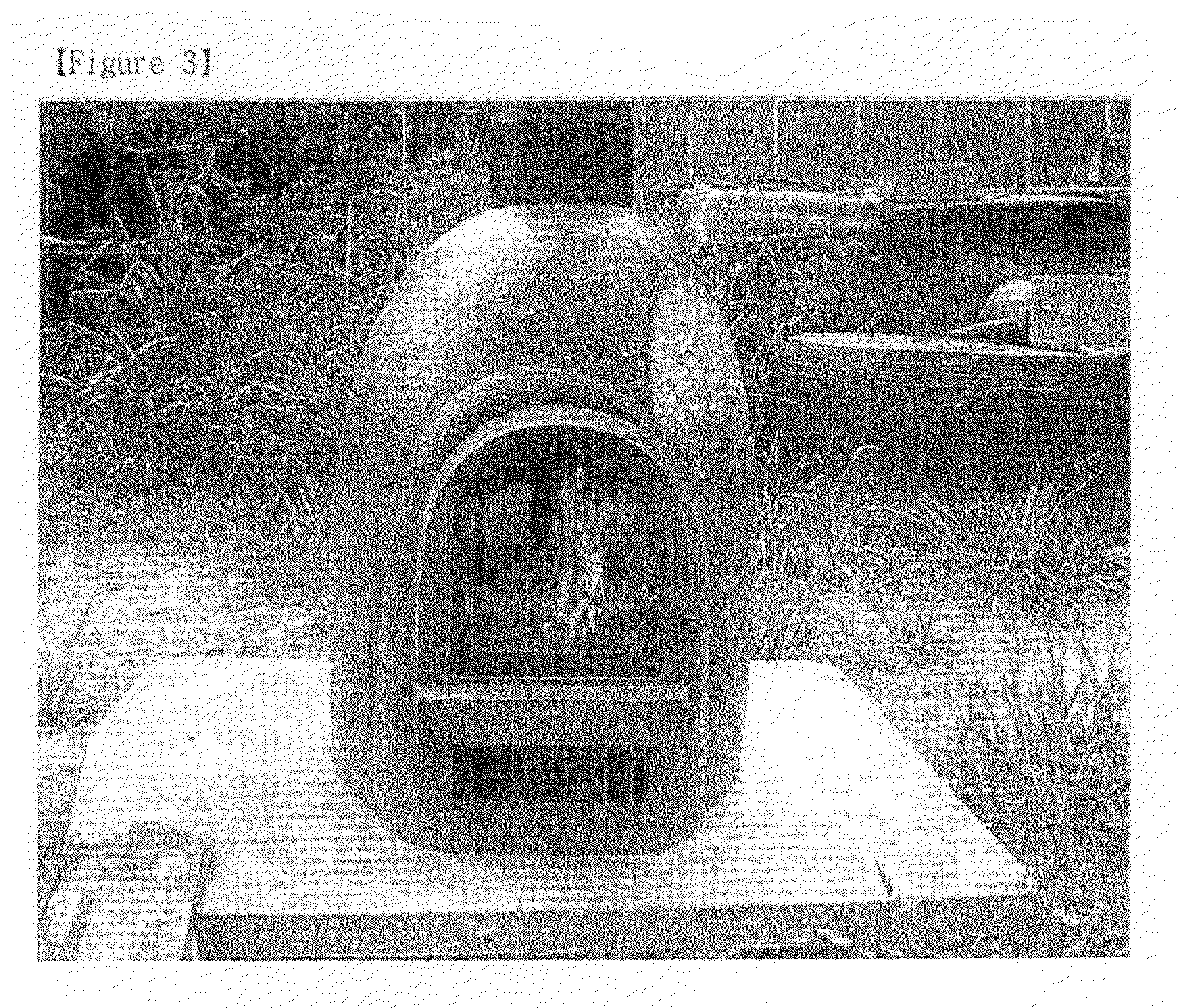
[0036]The photographs for sections of ceramic mouldings after firing were taken and the results are shown in FIGS. 1 and 2. From observation for the sections, it can be ascertained that the ceramic moulding according to the present invention was formed as dual structure having black carbon layer therein.

example 2

[0037]A composition was mixed in a component ratio described in Table 1 in Example 1, and was formed into stove form, and then the formed stove form were fired with oxidizing flames at 1200° C. to manufacture a ceramic stove.

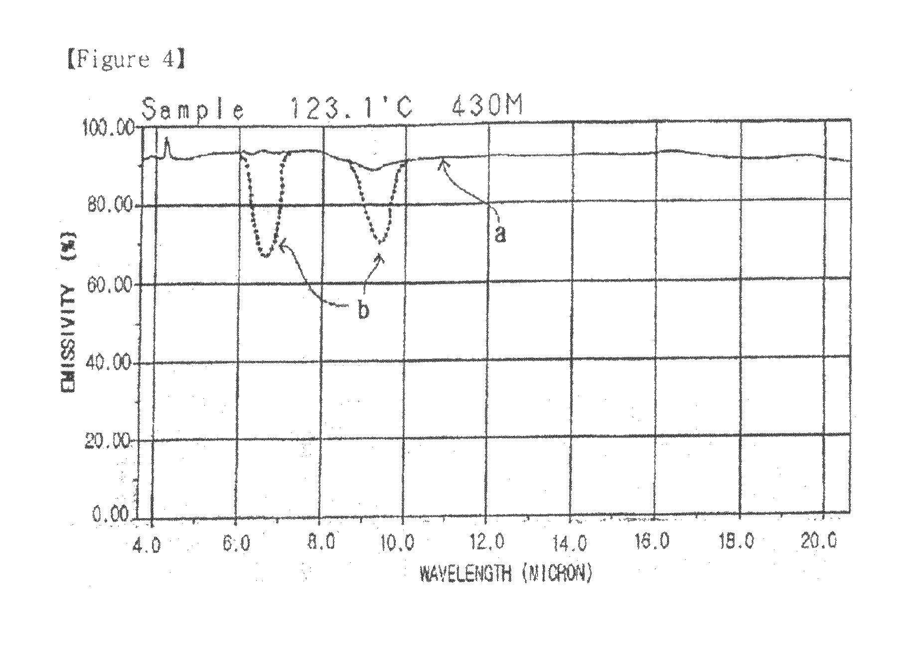
[0038]Usual ceramics tend to be cracked and broken easily at quick heating or quenching circumstance. However, the ceramic stove manufactured according to the present invention as shown in FIG. 3 has high fire resistance and heat resistance, and accordingly is not cracked even at quick heating or quenching circumstance which occurs when making a fire and cooling. Further, it can be found that the ceramic moulding manufactured according to the present invention has superior adiabatic property since one does not get burned in the hand even on touching the outside of the stove when the inner temperature of the stove exceeds 900° C.

[0039]When a ceramic stove is manufactured with a ceramic moulding with a carbon layer according to the present invention, the effect of...


PUM

PropertyMeasurementUnit
Temperatureaaaaaaaaaa
Percent by massaaaaaaaaaa

Abstract

Disclosed herein is a composition comprising 50 to 73% by weight of loess, 9 to 20% by weight of clay, 3 to 10% by weight of wood flour, 3 to 7% by weight of lignum carbonized carbon body powder, 11 to 15% by weight of water and 1 to 5% by weight of ceramic glaze to manufacture a ceramic moulding including a carbon layer therein. Preferably, the composition according to the present invention further comprises elvan powder and Schmotte. Meanwhile, the present invention also provides a method of manufacturing a ceramic moulding with a carbon layer comprising forming a moulding out of the composition and firing the formed moulding with oxidizing flames.

Description

TECHNICAL FIELD [0001]The present invention relates to a composition for a ceramic moulding of dual structure including a carbon layer therein, and a method of manufacturing a ceramic moulding using the same, wherein the composition comprises loess, clay, wood flour, lignum carbonized carbon body powder and a ceramic glaze.BACKGROUND ART [0002]A conventional typical clay brick is manufactured by mixing clay and quartz sand, drying the mixture and then firing at temperatures of 1100 to 1200° C. Such clay brick has a shortcoming in that a completed clay brick is heavy since a mixture of clay and quartz sand is comparatively heavy.[0003]Thus, in order to lessen the weight of a clay brick, a brick further comprising wood flour such as sawdust or chaff in the mixture of clay and quartz sand has been suggested. However, such brick has shortcomings in that wood flour remains partially as a carbon body due to firing flames in firing process, or is burned out completely thereby forming a por...

Claims


Application Information

Patent Timeline
IPC IPC(8): C04B33/04C04B33/32
CPCC04B33/04C04B33/13C04B2235/36C04B2235/422C04B33/34C04B35/62209C04B2235/9646C04B2235/3201C04B2235/3206C04B2235/3208C04B2235/3232C04B2235/3272C04B2235/72C04B35/6263C04B14/10C04B14/14C04B14/32C04B16/02
Inventor KIM, KOO-HAN
Owner KIM KOO HAN
Learn More