Control device and control method for vehicle power transmission device

a technology of power transmission device and control device, which is applied in the direction of machines/engines, instruments, gearing, etc., can solve the problems of sealing component parts, the possibility of reducing the durability of various components and the like, and the lik

Inactive Publication Date: 2013-02-05
TOYOTA JIDOSHA KK
View PDF24 Cites 7 Cited by
  • Summary
  • Abstract
  • Description
  • Claims
  • Application Information

AI Technical Summary

Benefits of technology

[0007]The invention provides a control device and a control method for a vehicle power transmission device that includes an electrical differential portion and an engagement device and that prevents excessively high rotation speed of a rotating element of the differential mechanism at the time of an engine stop control.

Problems solved by technology

Thus, there is possibility of decline of the durability of various components and the like, including the seal component parts and the bearings that support the differential mechanism.

Method used


Image

  • Control device and control method for vehicle power transmission device
  • Control device and control method for vehicle power transmission device
  • Control device and control method for vehicle power transmission device

Examples


Embodiment Construction

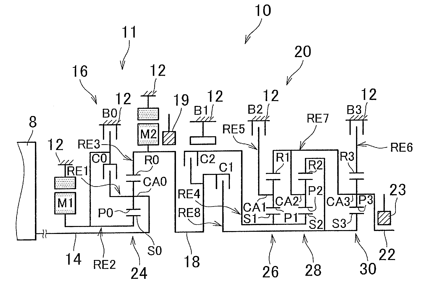
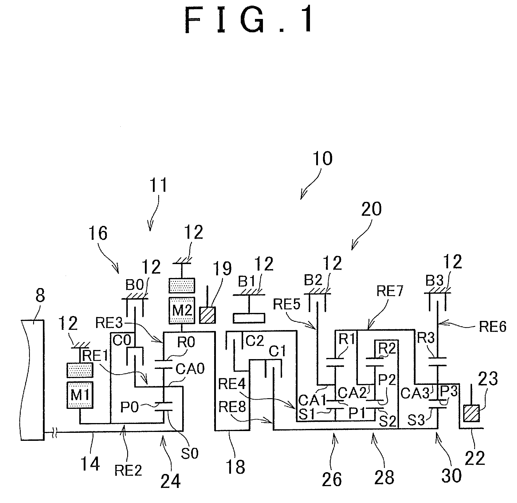
[0042]FIG. 1 is a skeleton diagram illustrating a transmission mechanism 10 that constitutes a portion of a power transmission device for a hybrid vehicle to which the control device of the invention is applied. In FIG. 1, the transmission mechanism 10 includes an input shaft 14 as an input rotating member, a differential portion 11 that is linked directly to the input shaft 14 or indirectly thereto via a pulsation absorbing damper (vibration damping device) (not shown), an automatic ratio shift portion 20 as a ratio shift portion that functions as a stepped-ratio transmission that is linked in series in the power transmission path between the differential portion 11 and driving wheels 38 (see FIG. 6) via a transmission member (corresponds to an output shaft of a differential mechanism) 18, and an output shaft 22 as an output rotating member that is linked to the automatic ratio shift portion 20. These members of the transmission mechanism 10 are disposed on a common axis within a t...


PUM


Abstract

When an engine stop control is executed while an automatic ratio shift portion is in a neutral state, a switching clutch is operated, so that a differential portion carrier of a differential portion planetary gear device that is linked to an engine, and a differential portion ring gear linked the automatic ratio shift portion are integrally rotated. Therefore, along with the engine stop control, the rotation speed of the rotating elements of the differential portion planetary gear device is reduced while the rotating elements are integrally rotated or substantially integrally rotated. Since the rotating elements are rotated integrally or substantially integrally, the high rotation speed of the differential portion ring gear linked to the automatic ratio shift portion, which tends to have a heightened rotation speed particularly during the neutral state, is prevented.

Description

INCORPORATION BY REFERENCE[0001]The disclosure of Japanese Patent Application No. 2007-238476 filed on Sep. 13, 2007 including the specification, drawings and abstract is incorporated herein by reference in its entirety.BACKGROUND OF THE INVENTION[0002]1. Field of the Invention[0003]The invention relates to a control device and a control method for a vehicle power transmission device. In particular, the invention relates to an engine stop control during a neutral state in a vehicle power transmission device that includes an electrical differential portion in which the differential state of a differential mechanism is electrically controlled and an engagement device that constitutes a portion of a power transmission path.[0004]2. Description of the Related Art[0005]There is a known vehicle power transmission device that includes an electrical differential portion in which the differential state between the rotation speed of an input shaft and the rotation speed of an output shaft is ...

Claims


Application Information

Patent Timeline
Patent Type & Authority Patents(United States)
IPC IPC(8): G06F7/00B60K6/445B60K6/547B60L50/16B60W10/06B60W10/08B60W10/10B60W20/00F02D29/00F02D29/02F16H48/295F16H48/30F16H48/32
CPCB60K6/442B60K6/445B60W10/105B60W30/192B60W20/00Y10T477/606Y02T10/6234Y02T10/6239Y10T477/675Y02T10/62B60W2710/081B60W2710/0644B60W20/30B60W10/10B60W2510/02
Inventor KUMAZAKI, KENTAMATSUBARA, TOORUTABATA, ATSUSHI
Owner TOYOTA JIDOSHA KK
Why Eureka
Try Eureka