Bonnet structure

a technology of elastic sealing and bonnet, which is applied in the direction of superstructure subunits, vehicle components, vehicle bodies, etc., can solve the problems of excessive abrasion of the elastic sealing member on the shroud side and/or the elastic sealing member on the bonnet side, and achieve the effect of facilitating connecting and detaching work, and stabilizing the support of the intake pip

Active Publication Date: 2013-02-12
YANMAR POWER TECHNOLOGY CO LTD
View PDF13 Cites 21 Cited by
  • Summary
  • Abstract
  • Description
  • Claims
  • Application Information

AI Technical Summary

Benefits of technology

[0012]The present invention has been achieved in view of these problems of the conventional art, and it is an object thereof to provide a bonnet structure applied to a working vehicle including a radiator, a cooling fan, and an engine, which are disposed in order from the front to the rear of the vehicle, a shroud that surrounds the cooling fan, an air cleaner that is disposed in front of the shroud, an intake pipe that has a first end connected to the air cleaner and a second end connected to an inlet port of the engine, and a bonnet that is rotatable about a rotary shaft along a vehicle width direction so as to be located at a closed position for covering these members and at an opened position for exposing these members, the bonnet structure being capable of effectively preventing the excessive abrasion and the detachment of elastic sealing members for sealing the gap between the bonnet and the shroud when the bonnet is located at the closed position.

Problems solved by technology

This results in defects such as excessive abrasion of the shroud-side elastic sealing member and / or the bonnet-side elastic sealing member, and detachment of the shroud-side elastic sealing member and / or the bonnet-side elastic sealing member from the shroud and / or the bonnet in some cases.

Method used


Image

  • Bonnet structure
  • Bonnet structure
  • Bonnet structure

Examples


Embodiment Construction

[0060]Described below is a bonnet structure according to a preferred embodiment of the present invention with reference to the accompanying drawings.

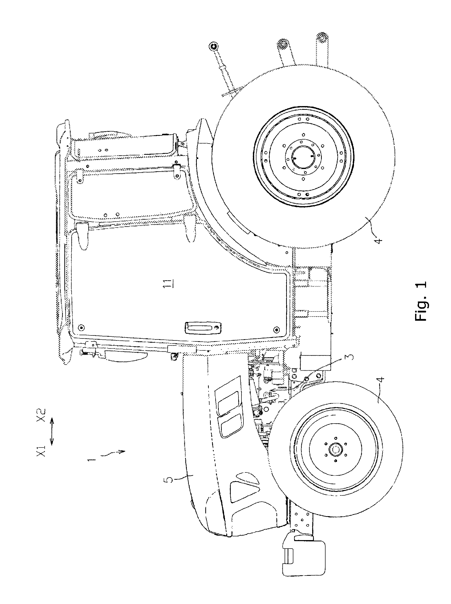
[0061]FIG. 1 is a left side view of a working vehicle 1 to which a bonnet structure according to an embodiment of the present invention is applied.

[0062]As shown in FIG. 1, the working vehicle 1 is configured as a tractor to which a working device is mountable.

[0063]As shown in FIG. 1, the working vehicle 1 includes a vehicle frame 2, an engine 3 that is supported by the vehicle frame 2, a pair of right and left travel units 4 that are driven by the engine 3, and a bonnet 5 that surrounds the engine 3.

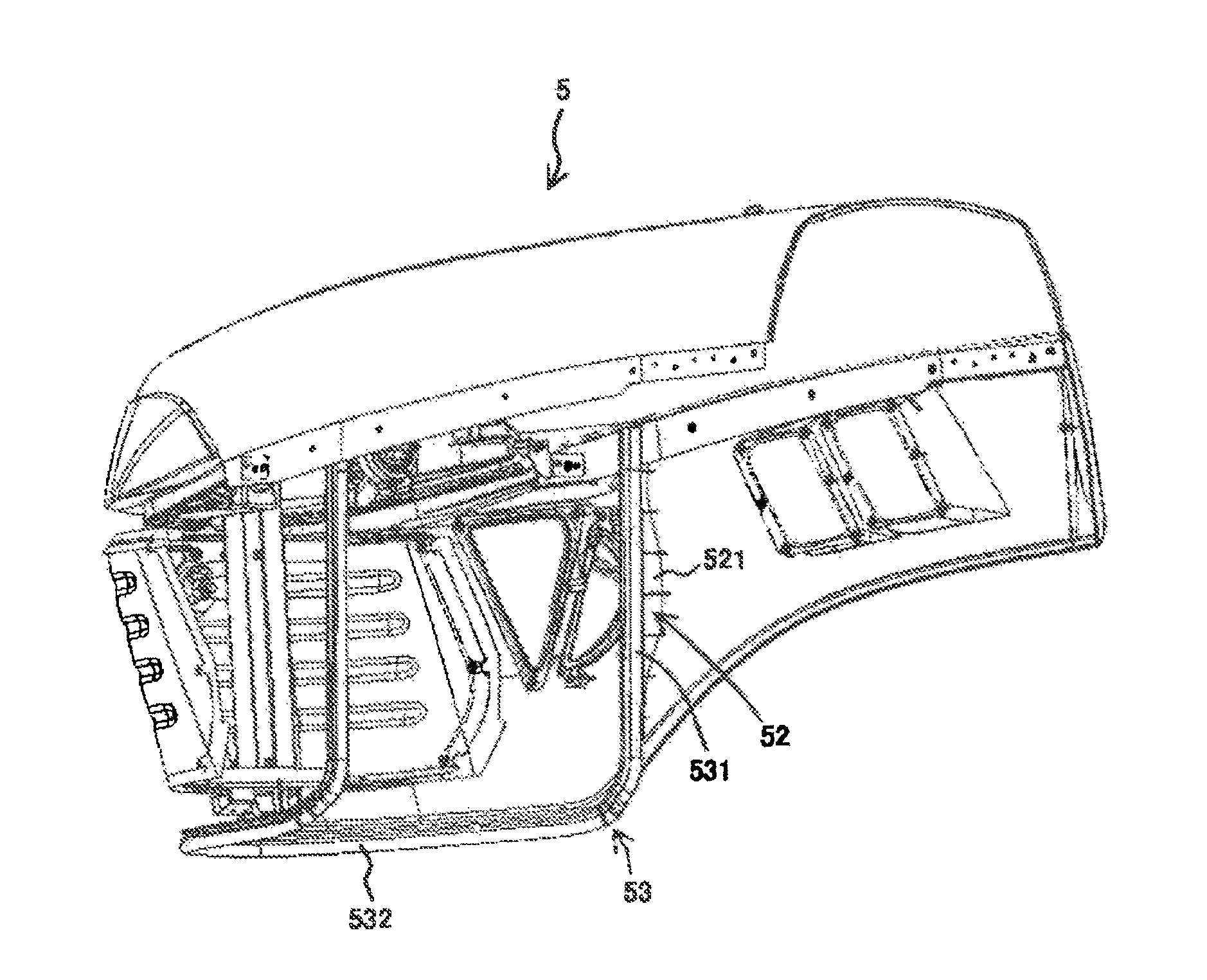
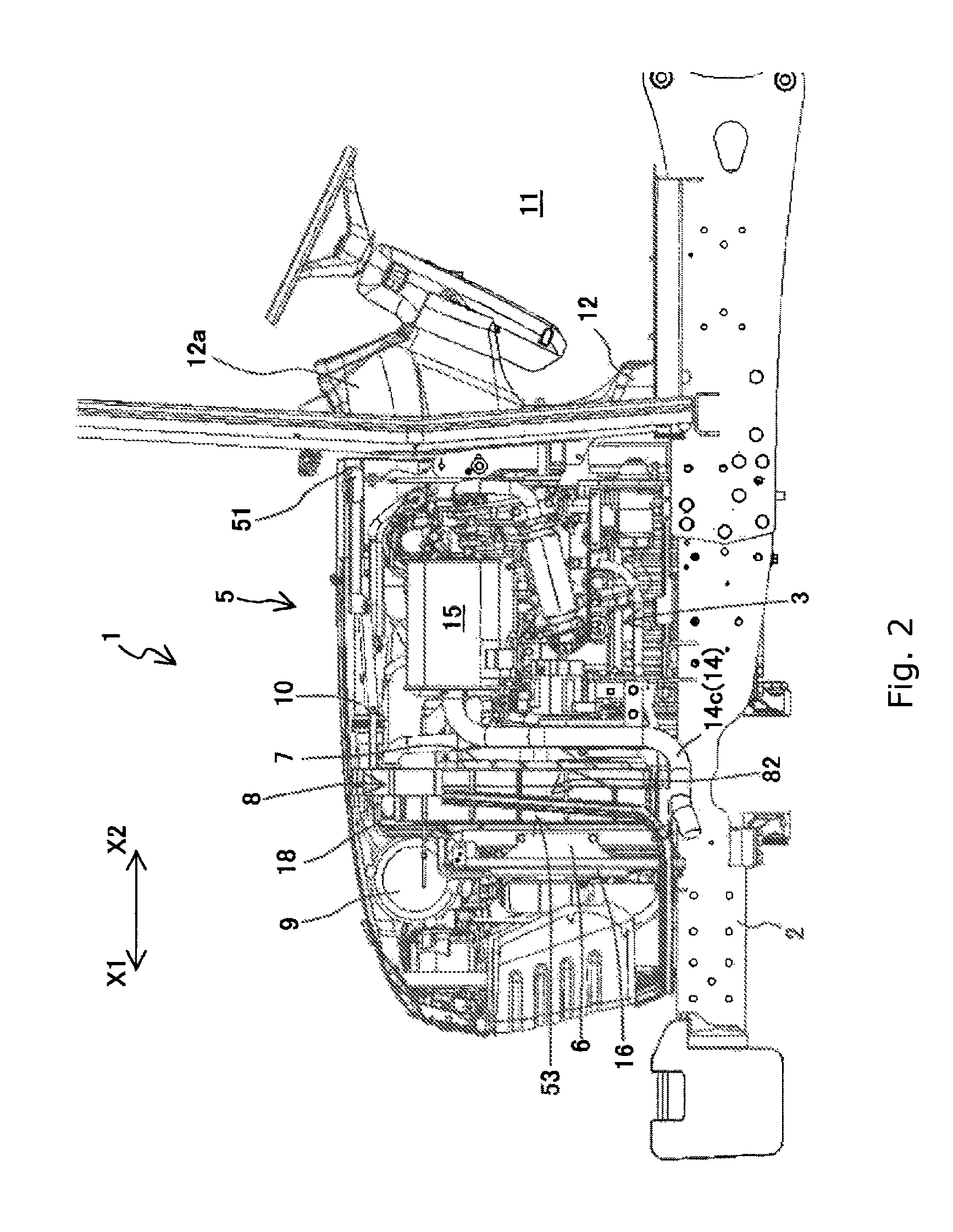
[0064]FIGS. 2 and 3 are a left side view and a plan view each showing an inner portion of the bonnet 5 in the working vehicle 1. FIG. 4 is a left side view in a state where the bonnet 5 in the working vehicle 1 is located at an opened position.

[0065]As shown in FIGS. 2 to 4, in the bonnet 5, there are provided in front of the engine 3 a ra...


PUM


Abstract

A bonnet structure including a bonnet flange extending inward from an inner peripheral surface of a bonnet is positioned farther toward a first direction, which is opposite in a vehicle longitudinal direction to a rotary shaft for the bonnet, than shroud flanges extending outward from side surfaces of a shroud main body when the bonnet is located at a closed position. A first elastic sealing member mounted to the bonnet flange is brought from the first direction into contact with anteroposterior contact surfaces of the shroud flanges that face to the first direction when the bonnet is rotated about the rotary shaft from the opened position to the closed position. It is possible to effectively prevent an excessive abrasion and a detachment of elastic sealing members for sealing a gap between the bonnet and the shroud.

Description

FIELD OF THE INVENTION[0001]The present invention relates to a bonnet (bonnet) structure applicable to a working vehicle including a radiator, a cooling fan and an engine, which are disposed in order from a front to a rear of the vehicle, a shroud that surrounds the cooling fan, an air cleaner that is disposed in front of the shroud, an intake pipe that has a first end connected to the air cleaner and a second end connected to an inlet port of the engine, and a bonnet that is rotatable about a rotary shaft along a vehicle width direction so as to be located at a closed position for covering these members and at an opened position for exposing these members.BACKGROUND ART[0002]There has been a working vehicle including a radiator, a cooling fan and an engine, which are disposed in order from the front to the rear of the vehicle, a shroud that surrounds the cooling fan, an air cleaner that is disposed in front of the shroud, an intake pipe that has a first end connected to the air cle...

Claims


Application Information

Patent Timeline
Patent Type & Authority Patents(United States)
IPC IPC(8): B62D25/10
CPCB62D25/10B62D25/12
Inventor KAWASHIRI, SHINYAMATSUI, YUTAKA
Owner YANMAR POWER TECHNOLOGY CO LTD
Why Eureka
Try Eureka